We review PLC PCB and PCBA designs for fabrication, assembly, inspection and test before production. Our engineers examine the complete manufacturing package and focus on the interfaces that commonly create industrial-control risk: field I/O, power conversion, communication, connectors, thermal features, isolation, coating and test access.
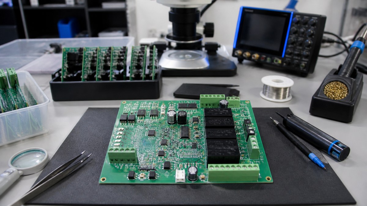
You receive specific DFM questions and approved dispositions linked to the released revision. We do not redesign the circuit or claim to validate system performance; we show whether the intended construction can be built, inspected and repeated without silently changing your design.
PLC DFM Review Map
| Design area | What we check | Customer result |
|---|---|---|
| Fabrication package | Stack-up, drill, copper, finish, dimensions and file consistency | Resolved PCB construction |
| Power and field I/O | High-current geometry, isolation features and terminal interfaces | Manufacturing-risk questions |
| Assembly | Land patterns, polarity, spacing, thermal mass and access | Buildable placement and process route |
| Connectors and mechanics | Outline, holes, keep-outs, height and insertion forces | Controlled interface information |
| Inspection and test | Visible and hidden joints, test points, programming and function | Proposed evidence route |
We First Reconcile Every Manufacturing File
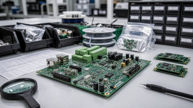
We compare Gerber or ODB++, drill data, stack-up, fabrication drawing, BOM, CPL, assembly drawing and mechanical information. Board outline, connector location, polarity, customer part and revision must agree.
When files conflict, we return the exact question before CAM or machine programming. The approved response becomes part of the product baseline.
Power and Field-I/O Areas Receive Focused Review
PLC boards often combine low-voltage logic with field power, relays, drivers and terminal blocks. We review copper definition, high-current features, creepage and clearance geometry, slots, barriers and board-edge conditions against the customer requirement.
Your design authority defines voltage, environment and applicable safety rules. We make the released spacing and construction manufacturable and identify any feature that production tolerances could reduce.
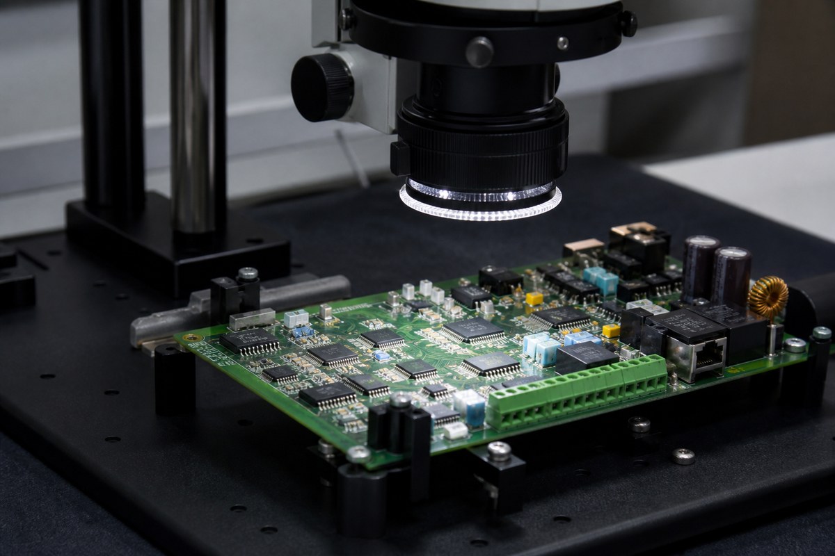
We Check Thermal Features for Fabrication and Assembly
Our review covers copper planes, thermal vias, exposed pads, heavy components, heat sinks and local thermal mass. We check whether the features can be fabricated and whether soldering, inspection and mechanical assembly remain practical.
When thermal mass changes the assembly route, we identify stencil, soldering, fixture or inspection considerations before release. Product operating temperature still requires system-level validation by the customer.
Fine-Pitch and Hidden Joints Need an Evidence Plan
We review pad, solder-mask and paste geometry for fine-pitch, QFN, BGA and other bottom-terminated packages. The inspection route may combine SPI, AOI and X-ray according to the defect risk.
We state which joints are visible, which require structural inspection and which electrical or functional questions need testing. This prevents an inaccessible joint from entering production without coverage.
Connectors and Mechanical Interfaces Must Match the Product
We check connector footprint, orientation, board edge, mounting holes, component height, enclosure keep-outs and assembly access. Terminal blocks and high-insertion-force connectors may also require support and soldering review.
Three-dimensional or mechanical data helps us identify conflicts that electrical files cannot show. Approved interface decisions remain with the released revision.
Coating and Cleanliness Requirements Affect Layout
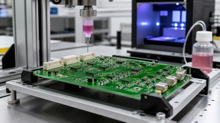
If the PLC assembly requires cleaning or conformal coating, we review coating keep-outs, connector contacts, test points, switches, heat sinks and masking access. The material, thickness, coverage, cure and acceptance requirement must be defined.
We convert the approved requirement into masking and inspection instructions so protection does not interfere with electrical or mechanical interfaces.
We Review Test Access Before Tooling
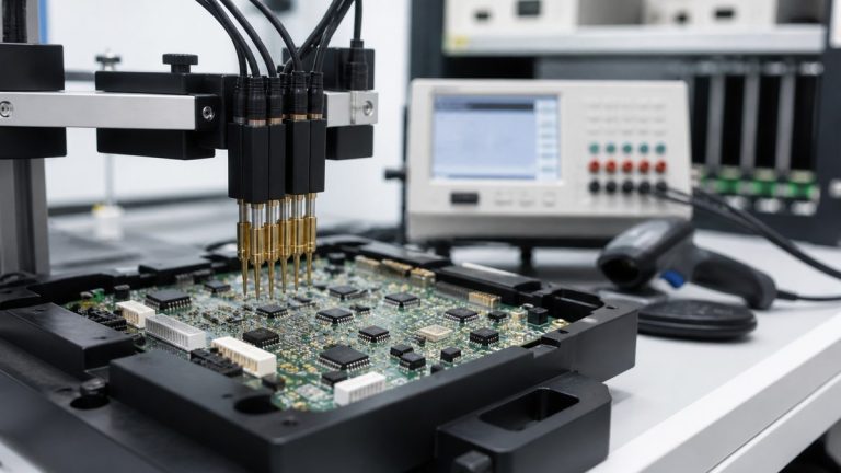
We check programming headers, test points, connector access, fixture clearance and the customer test procedure. ICT, flying probe and FCT have different access and data needs.
Early review avoids discovering after layout release that a required node or interface cannot be reached by the planned fixture.
What You Receive From Our PLC DFM Review
- file and revision conflicts;
- PCB construction and tolerance questions;
- assembly, polarity and access risks;
- connector and mechanical-interface questions;
- inspection and test coverage proposal;
- approved responses retained with the production release.
Send Your PLC Design for Manufacturing Review
Send Gerber or ODB++, stack-up, fabrication drawing, BOM, CPL, assembly drawing, mechanical data, operating voltage, field-I/O information, coating requirement, programming files, test procedure and quantities to sales@ebestpcba.com.
Our engineers will return the manufacturability questions, proposed route and evidence available for your PLC PCB or PCBA.