Rigid-Flex Material Engineering
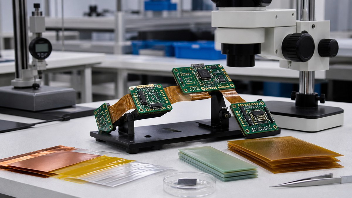
A rigid-flex PCB is a regional construction, not a rigid board with a flexible label. Rigid laminate, flexible dielectric, copper, coverlay, adhesives and stiffeners must work together through fabrication, assembly and the product’s bend condition. We review the released material system for manufacturability while the customer owns mechanical-life and system qualification.
Static and dynamic flex need different design inputs
Tell us whether the circuit bends once during installation or moves repeatedly, together with bend direction, radius, available length, cycle expectation and mechanical restraint.
No material name alone proves dynamic life. Qualification needs a defined construction and motion condition.
Rigid laminate supports components and interconnection
The rigid regions use an approved laminate and prepreg construction selected for electrical, thermal and mechanical requirements. Layer count, copper and thickness must be explicit by region.
Material alternatives require approval because they may change bonding and assembly behavior.
Polyimide film forms the flexible dielectric
Flexible regions commonly use polyimide dielectric with controlled thickness and material identity. Its mechanical and thermal properties interact with copper and adhesive choices.
EBest confirms the approved construction and does not treat all polyimide films as interchangeable.

Copper type and thickness influence bend behavior
Copper foil construction, thickness, grain behavior and routing geometry can affect flexibility. The customer specifies the approved copper and bend-related design rules.
Our fabrication review checks artwork and process compatibility; cycle life remains a validation result.
Adhesive and adhesiveless systems behave differently
Flexible laminates and coverlay may use different bonding approaches. Adhesive thickness, flow and thermal processing can influence total thickness and transition geometry.
The selected system must be compatible with the stack-up and assembly cycles.
Coverlay protects flex copper and defines openings
Coverlay material, thickness, openings and registration need clear data. Small webs, dense pads and connector fingers may challenge fabrication.
Solder mask and coverlay are not assumed interchangeable. The drawing identifies where each applies.
Stiffeners control termination and component regions
Polyimide or other stiffeners may support connectors, fingers and local components. We need type, thickness, outline, position and bonding requirement.
Mating fit requires the actual connector and finished interface tolerance.
Rigid-to-flex transitions need compatible materials
Material overlap, thickness steps, copper distribution and protective features affect the transition. Our review checks the released stack-up and geometry and flags features likely to create fabrication or handling risk.
Additional reinforcement is not added without authorization because it changes flexibility.
Surface finish and contacts need application context
Connector fingers, solderable pads and exposed contacts may need different finish, thickness or wear requirements. The customer identifies the mating and service condition.
We control the specified finish and applicable inspection, while contact-life qualification remains customer-defined.
Assembly materials and tooling protect flex areas
Fixtures support rigid regions and avoid uncontrolled creasing. Component, solder, cleaning, coating and adhesive materials must be compatible with the flex construction.
Handling and bend restrictions become visible work instructions.
Moisture and thermal history affect fabrication and assembly
Flexible materials and completed rigid-flex boards require appropriate storage and preparation for the selected process. The approved material guidance and customer restrictions inform handling, baking where applicable and exposure control.
Excessive or unapproved heat can affect materials, so preparation is not treated as an unlimited corrective action.
Panelization must support the flexible geometry
Rigid-flex panels need tooling, rails and temporary support that keep flexible sections stable through imaging, assembly and separation. Projecting tails and transition areas require protection from creasing and abrasion.
The panel and removal method are controlled as part of the manufacturing route.
Material substitutions trigger mechanical and electrical review
A change in laminate, polyimide, adhesive, coverlay, copper or stiffener can alter thickness, flexibility, bonding, impedance or assembly behavior. EBest identifies the proposed difference and does not release it as an equivalent without approval.
The customer determines whether new samples, bend tests, electrical measurements or system validation are required.
Rigid-flex material decision matrix
| Region or function | Material decision | Evidence or question |
|---|---|---|
| Rigid component area | Laminate, prepreg and copper stack-up | Approved regional construction |
| Moving flex area | Polyimide, copper and bend geometry | Manufacturing review; customer life test |
| Conductor protection | Coverlay and opening design | Registration and inspection |
| Termination | Stiffener and surface finish | Dimensional and mating requirements |
| Transition | Overlap, bonding and thickness change | DFM disposition and approved stack-up |
Testing and evidence remain condition-specific
PCB electrical testing can check continuity and isolation. Dimensional or structural inspection can cover selected construction features. Bend testing needs a fixture, radius, direction, cycles and acceptance supplied by the customer.
A continuity pass before bending does not prove dynamic durability.
Inputs for an EBest material review
- Rigid-flex data, drawing and regional stack-up.
- Approved laminate, flex film, copper and adhesive.
- Static or dynamic bend conditions.
- Coverlay, stiffener and transition details.
- Connector and finished thickness tolerances.
- Assembly and environmental conditions.
- Electrical, dimensional and bend tests.
- Material documents and change rules.
What EBest returns
Our engineers can return a regional construction review, material and availability questions, coverlay and stiffener findings, transition and assembly risks, inspection scope and available evidence. Send the bend condition with the material data so the selected build supports the actual mechanical use.
Discuss Your Project With Our Engineers
Send us your rigid-flex stack-up, bend zones, material restrictions, mechanical drawing and expected use condition. We will review the proposed production construction with your team.
Email sales@ebestpcba.com with the current revision and expected quantity.
For your rigid-flex project, we will confirm material regions, transition details and inspection points before release. You can approve the production construction against the mechanical and reliability conditions your product must meet.