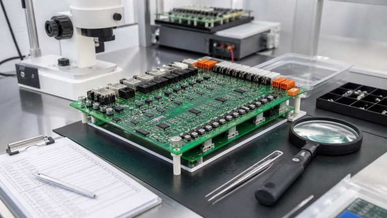
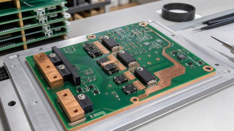
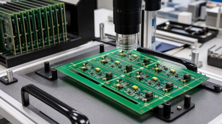
A metal-core PCB is useful when the design needs a short, controlled heat path from heat-generating components through the circuit layer and dielectric into a metal base. It is not automatically better than FR-4 for every power or new-energy product. Electrical isolation, routing density, multilayer needs, mechanical integration and total thermal path determine the choice.
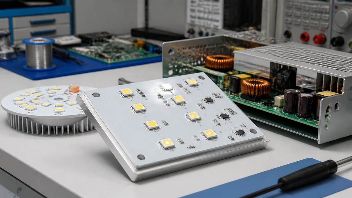
We manufacture metal-core PCBs from an approved copper, dielectric and metal-base construction. Our engineers review thermal intent, isolation, component interfaces, mechanical fit and assembly process, then return a buildable proposal and evidence plan.
Metal-Core PCB Selection Guide
| Design condition | Metal-core fit | What we review |
|---|---|---|
| Heat concentrated near power or LED components | Often useful when heat can flow directly to the base | Pad, dielectric, base and heat-sink interface |
| Complex multilayer routing | May be less suitable than a multilayer FR-4 or hybrid solution | Layer and interconnect requirement |
| High electrical isolation requirement | Possible only with an approved dielectric system | Voltage, dielectric thickness and test requirement |
| Mechanical base doubles as heat spreader | Can simplify the thermal interface | Flatness, holes, finish and mounting |
| Heat path is limited elsewhere | Metal core alone may not solve the system problem | Interface material, heat sink, airflow and enclosure |
We Start With the Complete Thermal Path
We ask for component losses, allowable temperature, board interface, heat sink, enclosure, airflow and ambient condition. The metal base only helps when heat can leave the component, cross the dielectric and continue into the mechanical system.
Your engineering team validates junction and system temperature. We manufacture the approved path and control its physical construction.
The Dielectric Layer Controls Thermal and Electrical Trade-Offs
The dielectric must provide electrical isolation while allowing heat transfer. Thickness, thermal conductivity, voltage requirement and processing compatibility must be considered together.
We review the specified material system and identify any availability or construction question before release. A higher headline conductivity does not replace actual thickness and interface design.
Copper Geometry Still Defines the Circuit
We review copper thickness, trace and spacing, pads, current paths and finished surface. Metal core does not remove the need for buildable copper geometry or controlled high-current transitions.
Where the design requires fine features and heavy copper together, we return the manufacturing trade-off for approval.
Isolation and Edge Geometry Need Clear Requirements
We check copper-to-edge distance, mounting holes, slots, metal exposure, component leads and any high-voltage boundary. The customer supplies the required voltage and applicable safety basis.
Electrical test or dielectric-withstand requirements, fixtures, limits and report needs are defined before production.
Mechanical Integration Is Part of the PCB
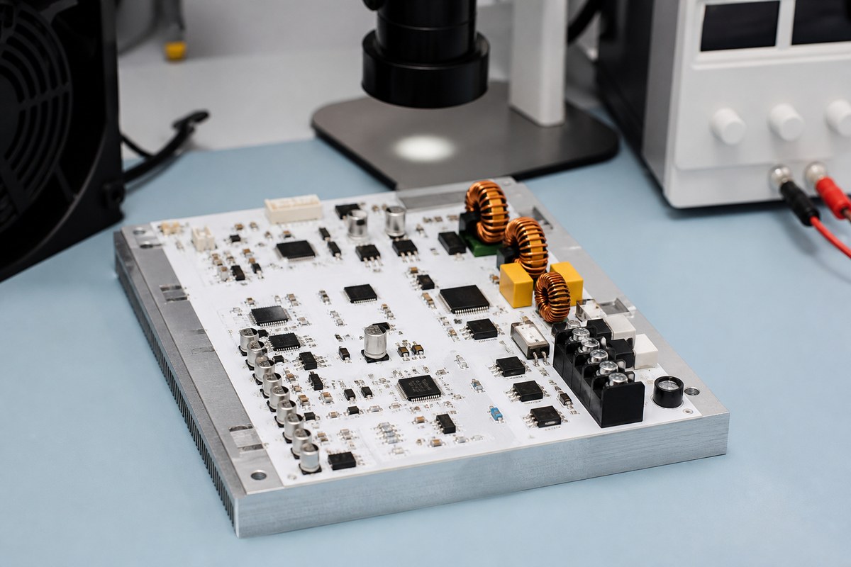
Metal-base thickness, flatness, outline, holes, countersinks, surface condition and mounting hardware affect the final thermal contact. We compare PCB and mechanical data so the board fits the heat sink or enclosure.
Critical dimensions and interface surfaces can enter the inspection plan.
Assembly Requires Thermal-Mass Planning
The metal base changes preheat, reflow, soldering and rework behavior. We review component packages, paste, thermal pads, fixtures and temperature exposure using the intended production construction.
SPI, AOI and applicable X-ray inspection verify assembly conditions according to the package risk.
When FR-4 May Be the Better Choice
FR-4 may be more practical when the design needs multilayer routing, controlled impedance, many through connections or a thermal path built with copper planes and vias. A separate heat spreader can also provide better system integration in some products.
We help compare manufacturability rather than recommending metal core only because it sounds more thermal.
What Evidence We Can Provide
The project can define material identity, stack-up, finished dimensions, electrical test, applicable dielectric test, inspection and shipment records. The evidence remains tied to the released lot and construction.
This lets your team verify what was manufactured while retaining system thermal qualification as a separate responsibility.
Send Your Metal-Core PCB Requirements
Send Gerber or ODB++, drawing, copper, dielectric and metal-base requirements, voltage, component losses, heat-sink or enclosure data, dimensions, quantities, assembly files and test needs to sales@ebestpcba.com.
We will return the proposed construction, trade-offs, DFM questions and evidence plan.