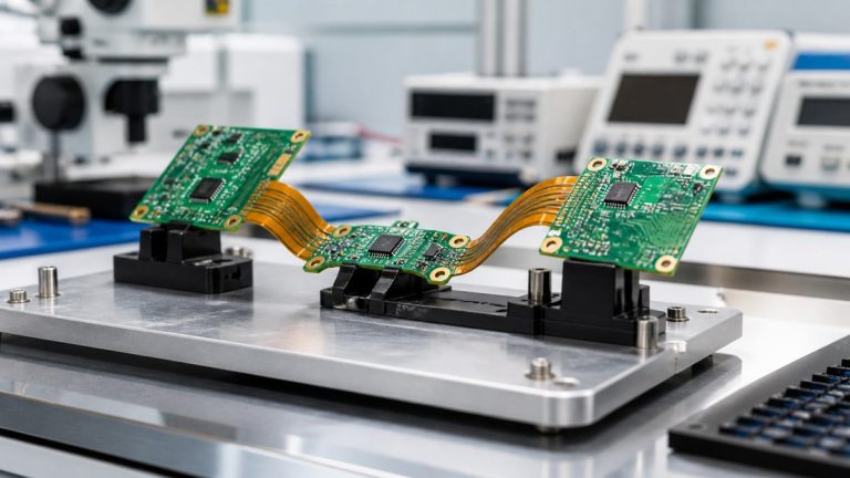
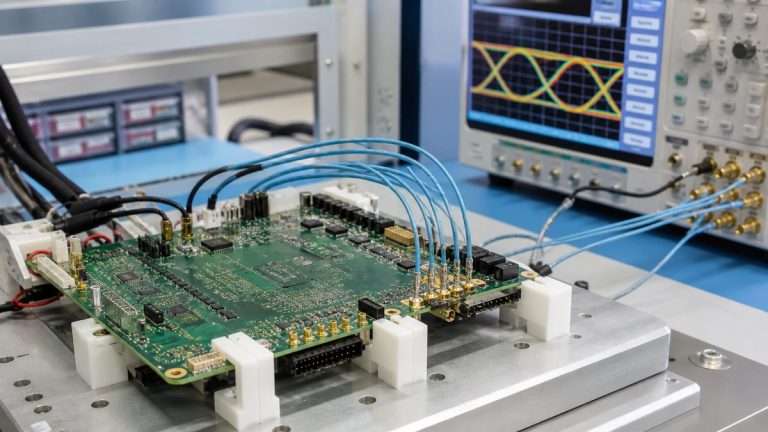
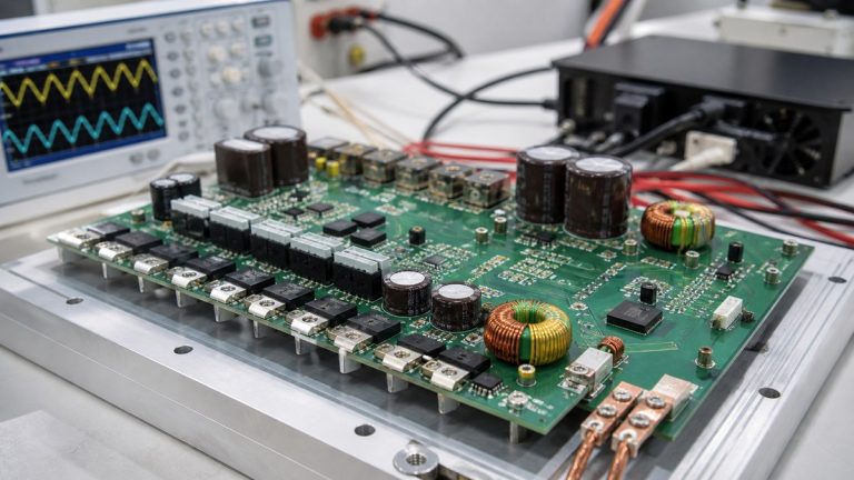
We inspect and test robotics PCBAs with a coverage route built around the actual assembly: processors, fine-pitch packages, sensors, communications, motor drivers, power joints, connectors and programmed devices. We use applicable SPI, AOI, X-ray, electrical and functional methods for the risks each one can detect.
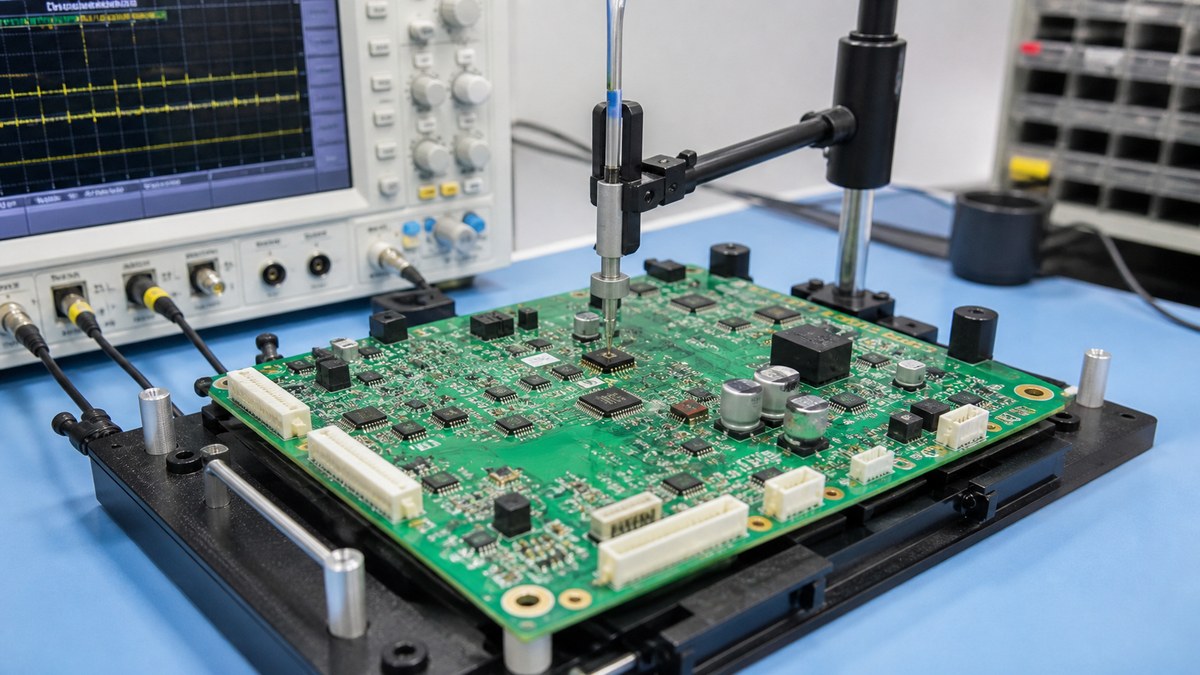
You receive product-linked results showing what was inspected or tested, the applicable program or procedure revision, the outcome and disposition. This gives your team evidence of both manufacturing quality and the defined electronic functions without pretending that one test proves the complete robot.
Robotics PCBA Coverage Matrix
| Risk | Our method | Evidence |
|---|---|---|
| Paste-printing variation | SPI where included | Recorded paste-process result |
| Visible placement or solder defect | AOI and visual inspection | Inspection result and disposition |
| Hidden BGA/QFN joint | Selected X-ray inspection | Applicable image or result |
| Wrong firmware | Controlled programming | Firmware identifier and result |
| Electrical connectivity | ICT, flying probe or defined electrical check | Program revision and result |
| Robot interface function | Customer-defined FCT | Procedure, limits and result |
We Build Coverage From the Product Risk
Our engineers review package mix, polarity, fine pitch, hidden joints, current paths, sensor inputs, communication interfaces, programming needs, test access and customer acceptance criteria.
Each important condition receives prevention, inspection or test coverage. Where a gap remains, we identify it before production so the design or test strategy can be changed deliberately.
SPI and AOI Control Different Assembly Stages
SPI checks applicable solder-paste deposits before placement hides them. AOI checks visible component identity, position, polarity and solder conditions after assembly.
Reaction rules control affected panels and process correction. These upstream checks reduce dependence on a later functional test to discover solder-process problems.
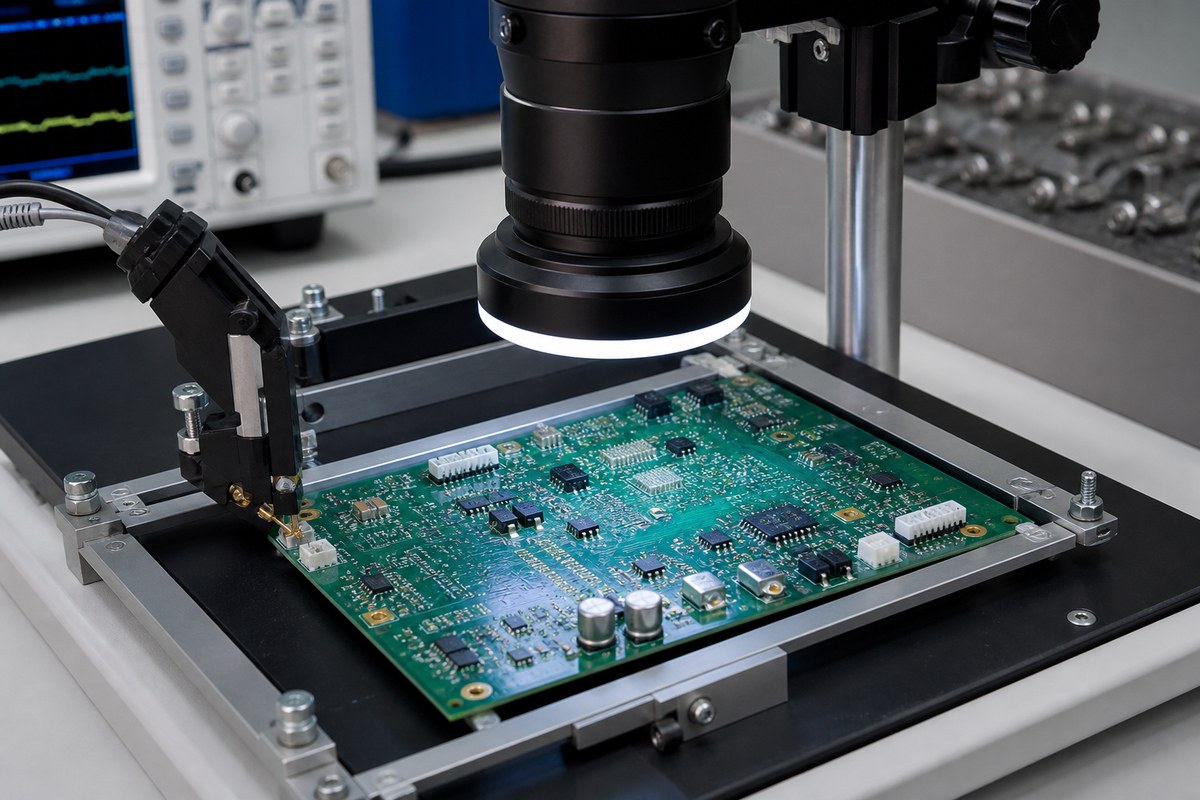
X-ray Supports Hidden-Joint Decisions
We use X-ray for selected BGA, QFN and other bottom-terminated packages where optical inspection cannot see the joint structure. The approved plan defines locations, coverage, acceptance and required image output.
X-ray does not prove electrical function or every solder condition. We combine it with the other controls needed by the assembly.
Programming Remains Part of Configuration Control
We control the approved firmware or programming file, target device, revision and required identifier. The programming result remains connected to the work order or product identifier where the route supports it.
Hardware or firmware changes trigger review of programming, fixture and test compatibility before release.
Electrical Tests Depend on Access and Purpose
ICT, flying probe or other electrical checks can verify defined connectivity and component conditions when the design and method provide suitable access. We review test points, isolation, fixtures, program ownership and expected volume.
The result identifies the product, method or program revision and disposition. Coverage is stated rather than assumed.
Functional Testing Uses Defined Robot Conditions
FCT may include power rails, communication, sensor channels, I/O, encoder interfaces or motor-control outputs according to the customer procedure. We require fixtures, cables, firmware, loads, expected responses and limits.
We state the tested functions. Mechanical motion, safety, full-load thermal performance and lifetime remain separate unless the approved test explicitly includes them.
Failures, Repairs and Retests Stay Visible
Failed units are contained and connected to diagnosis, approved repair or rework, verification and final result. Available work-order or serial-number links support retrieval.
This preserves the path from initial failure to release and helps later investigation of recurring conditions.
Why Robotics Customers Use Our Evidence Plan
We show which process and product risks are covered, which method addresses each risk and what result your team can receive. You can distinguish structural evidence, electrical checks and defined functional performance.
This provides a stronger production decision than a list of inspection machines or a simple final pass label.
Send Your Robotics Test Package
Send Gerber, BOM, CPL, assembly drawing, package list, firmware, programming instructions, test points, fixture data, sensor and communication requirements, motor-control test conditions, limits, quantities and report format to sales@ebestpcba.com.
We will return the proposed inspection and test matrix, missing inputs and evidence available for the build.