
Fine-Pitch BGA Escape
Use microvias and finer geometry when through-hole fan-out consumes routing channels or blocks power and ground access.
High-density interconnect manufacturing
EBest PCBA reviews laser microvias, blind and buried connections, fine-line routing and via-in-pad features for compact PCB builds. Send your stack-up, via specifications and board files to confirm the fabrication structure and quotation scope.
We aim to provide an initial engineering response within 24 hours. Construction, pricing, test requirements and production lead time are confirmed from the design files.
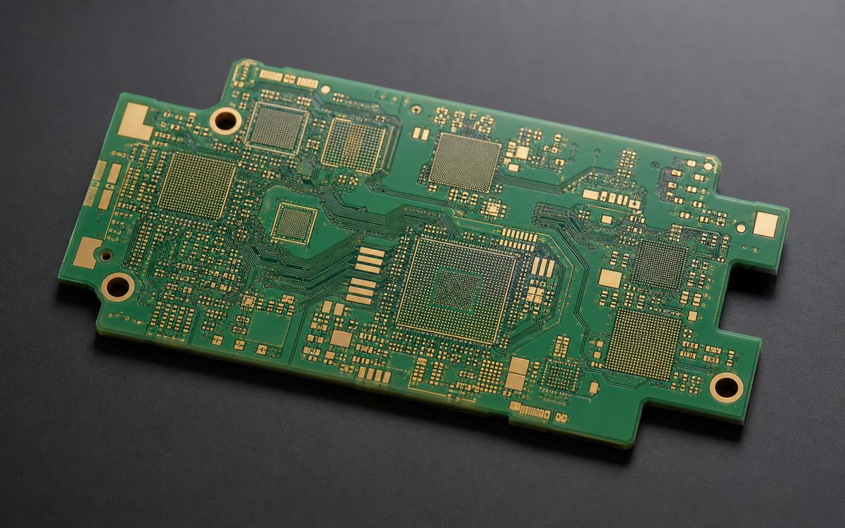
Start with the design constraint
HDI affects the stack-up, drilling sequence, registration, copper balance, and cost, so it should be considered before the layout is finalized.
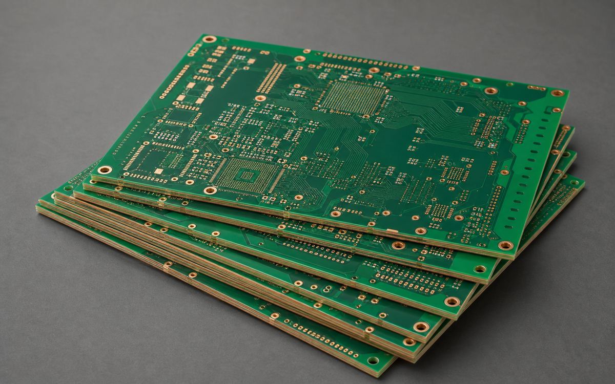
Use microvias and finer geometry when through-hole fan-out consumes routing channels or blocks power and ground access.
Reduce board area while balancing layer count, dielectric thickness, routing density, and reliability.
Move selected connections between layers while controlling drill depth, target land, plating and sequential lamination requirements.
Review fill, planarization, cap plating, pad size, and assembly requirements before approving the VIPPO structure for fabrication.
Construction selection
Each additional build-up cycle adds process time and tighter registration requirements. EBest PCBA confirms the required structure from the layer connectivity, via map, and approved stack-up.
Required layer transitions determine the number of laser-drilling and lamination cycles. Cost and lead time depend on the final build-up structure.
Standard structures and items requiring additional review are identified before quotation.One build-up layer on each side of the core structure, with the via map approved. N denotes the core-layer structure.
Two build-up layers on each side where additional transitions are required, subject to stack-up and process review.
Selected layer-to-layer structures subject to complete connectivity and process evaluation.
HDI Capability Review From Your Production Files
The stack-up, via map and copper define the approved HDI construction. The references below are evaluated as a complete build.
| Capability | Production Reference | Conditions / Special Review |
|---|---|---|
| Laser microvia | 0.10 mm reference | Hole-size definition, dielectric depth, aspect ratio, capture pad and plating or fill confirmed. |
| Finished mechanical hole | 0.20 mm minimum reference | 0.15 mm by review; board thickness, plating and tolerance confirmed. |
| Inner line width / spacing | 4 / 4 mil at 0.5–1 oz copper reference | 3 / 3 mil by review; base and finished copper, etching and layer-specific geometry confirmed. Outer layers assessed separately. |
| Through-hole aspect ratio | Up to 8:1 reference | Up to 10:1 by review; hole size, thickness and plating must form an approved combination. |
| HDI build-up | 1+N+1 after stack-up review | 2+N+2, stacked or staggered microvias and Any-Layer by project evaluation. |
| Total layer count | Defined by the approved HDI stack | Build-up layers, core structure, registration and lamination sequence determine the construction. |
| Via-in-pad / VIPPO | Selected filled, planarized and capped structures | Via type, copper or specified fill material, cap plating, pad flatness and assembly requirements confirmed. |
| Surface finish | Selected for the approved assembly interface | OSP, ENIG, silver or tin; HASL where pad flatness permits; ENEPIG or hard gold by review. |
| Controlled impedance | Target and tolerance agreed from the stack-up | Material data, dielectric thickness, finished copper, reference planes, coupons and testing confirmed. |
Line width and spacing are separate dimensions. A 0.10 mm microvia reference does not determine allowable depth or stacked-via qualification. The quotation confirms the complete construction and inspection or reliability scope. For conventional layer options, see FR4 and multilayer PCB capabilities.
HDI Manufacturing Process
The exact process depends on the approved build-up, materials, and inspection plan. Each lamination and drilling cycle is checked against the approved stack-up and via structure.
Check layer connectivity, microvia depth, target lands, copper and impedance requirements.
Control dielectric, laser depth, target lands and registration for each build-up cycle.
Metallize and plate the approved interconnections. Apply specified microvia copper fill or selected mechanical-via resin fill according to via type, with planarization and cap plating where required.
Protect fine geometry, copper balance and impedance-critical routing through production.
Confirm ENIG, OSP or project-specific finish against BGA, via-in-pad and soldering needs.
Complete electrical testing and agreed dimensional, microsection and final inspection. Qualification tests follow a separately agreed plan.
Engineering and inspection evidence
Confirm target-land interfaces, specified copper fill, registration and cap-plated pad requirements. Mechanical-via resin fill and cap plating are defined separately from microvia copper fill.
Review missing inputs, drill definitions, via-to-pad geometry, copper weight and the build sequence before quotation.
Confirm target-land access, annular relationships and layer alignment through the sequential build-up.
Microsections assess specified plating, fill and interfaces. Reflow, thermal-stress and other reliability qualification require agreed coupons, methods and acceptance criteria.
Perform electrical testing and impedance verification against the approved data and coupon plan.

Supported HDI constructions
Match your BGA escape, signal-integrity and assembly requirements to the construction profiles below. Each build follows an approved stack-up and via map.
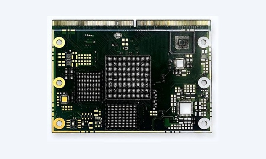
Microvia fan-out assessed with BGA pitch, capture pads and routing channels.
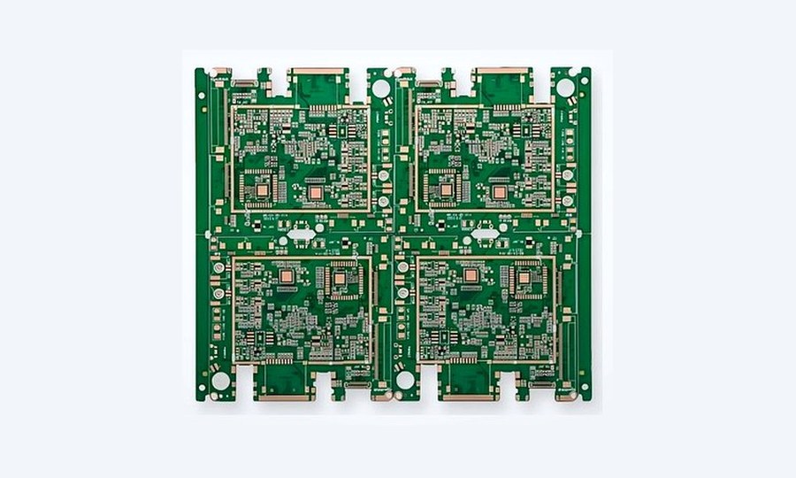
Reference planes, dielectric data and layer transitions aligned with the impedance plan.
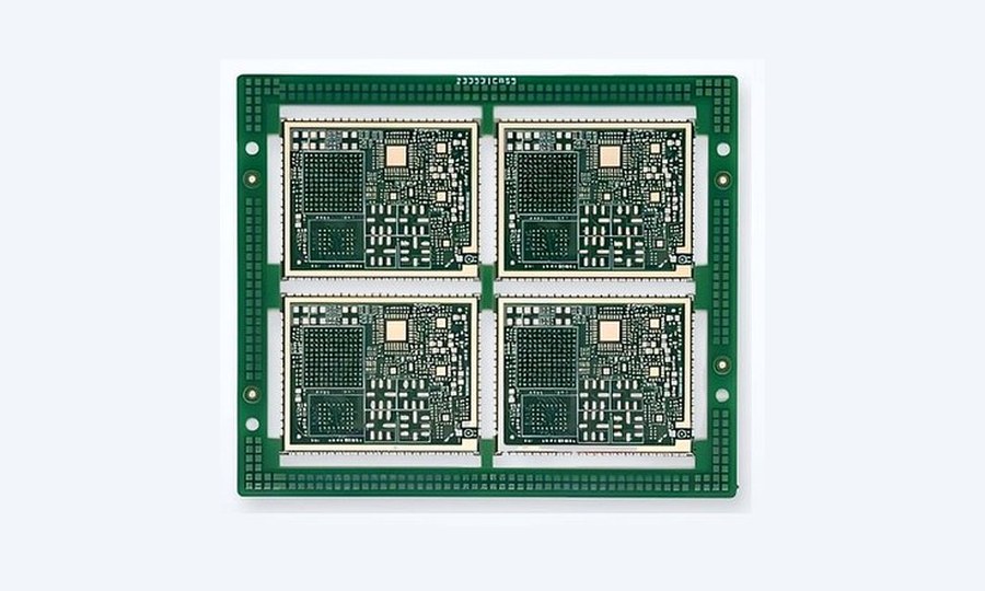
Material, power routing and fine geometry selected for the assembly and service requirements.
Industry applications

Compact processors and communication interfaces with signal-integrity requirements.

Compact sensing or monitoring modules with defined documentation needs.

Selected sensing and control boards with defined thermal and mechanical requirements.

Dense embedded controllers and communication assemblies.
Prepare a quote-ready review
Send your available design data, stack-up and via map. We will identify missing information, review the required build structure and confirm the quotation scope.
Share the files you have. Our team will review the stack-up, microvias, copper and assembly requirements, then confirm the next steps for pricing and production.