

01 / AVIONICS ENGINEERING
Aerospace PCB DFM & Engineering Review
Review Gerber files, stack-up, materials, impedance, tolerances, and assembly requirements before production.
Review avionics PCB layout →EBest PCBA supports aerospace and avionics electronics from PCB fabrication and component sourcing to assembly, inspection, testing, and traceability. Production is controlled against approved files, BOM requirements, and project-specific quality criteria.
 Aerospace Electronics Application
Connect avionics PCB layout, aerospace PCB prototyping, controlled fabrication, approved sourcing, assembly, inspection and release evidence against one project baseline.
Review Gerber files, stack-up, materials, impedance, tolerances, and assembly requirements before production.
Review avionics PCB layout →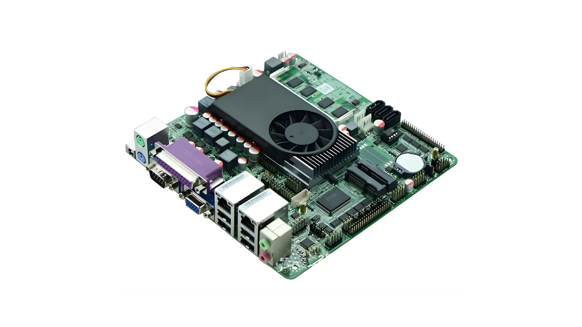
Build prototypes and pilot lots to verify PCB construction, assembly readiness, inspection requirements, and production documentation.
Review aerospace PCB prototypes →
Manufacture aerospace PCBs with approved materials, controlled revisions, defined process requirements, and production traceability.
Review aerospace PCB production →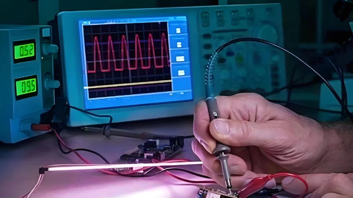
Support SMT/THT assembly, SPI, AOI, X-Ray, electrical testing, and functional testing according to project requirements.
Review aerospace PCBA →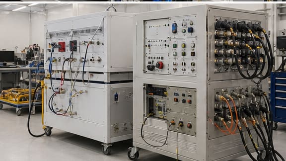
Aerospace PCB/PCBA projects require control of materials, signal integrity, component sources, inspection, traceability, and design changes from engineering through production and service.
Confirm materials, thermal limits, vibration resistance, and mechanical support for the intended operating environment.
Maintain the required stack-up, impedance, dielectric properties, reference planes, and critical routing geometry.
Control approved sources, lifecycle status, alternates, and substitutions before any component change is made.
Keep materials, processes, inspection, test, and revision records tied to the approved build.
Application requirements determine the materials, electrical and mechanical construction, reliability controls and required documents. Final manufacturing requirements are confirmed from your project files.

Control, display, navigation and interface electronics where approved revisions, signal integrity and verification evidence must remain aligned.
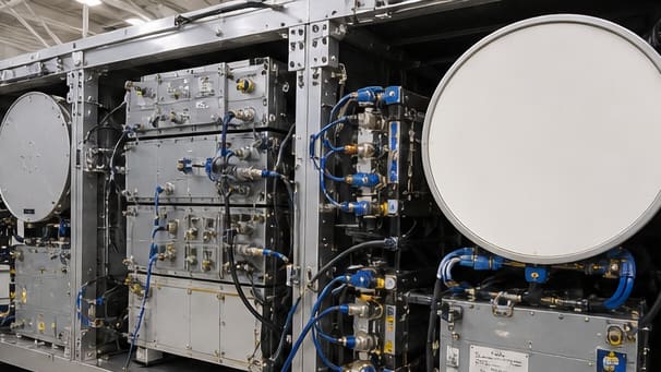
Material, controlled impedance, RF launch, grounding, thermal and inspection requirements reviewed as one electrical construction.
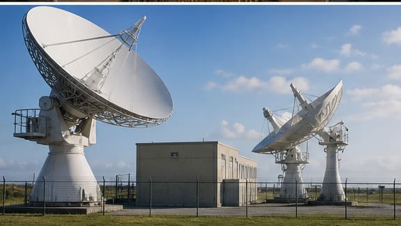
High-speed, timing, power and interface decisions coordinated with stack-up, component control, assembly and project-defined testing.
Current paths, copper, insulation, heat transfer, component spacing and mechanical integration reviewed before fabrication release.
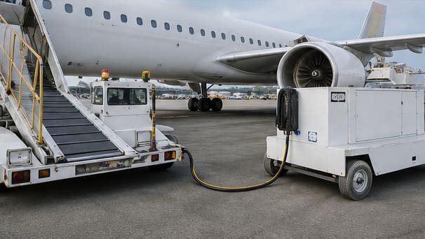
Robust control, interface and power assemblies prepared for service access, repeat production, inspection and controlled maintenance records.
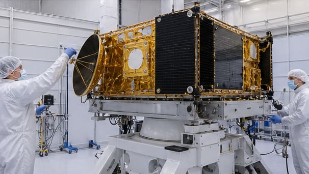
Project-specific material, cleanliness, thermal, reliability, documentation and release requirements separated from routine constructions before quotation.
Published capabilities are screening references. The approved quotation records the construction, tolerances, inspection, test coverage, schedule and release conditions for the actual files.

Your aerospace PCB or PCBA project moves through a defined process from file review and prototype validation to production, testing, and final records. Each stage is confirmed against the approved project requirements before moving forward.
Confirm available files, BOM, quantities, quality requirements, test needs, and NDA requirements.
Review stack-up, materials, impedance, tolerances, assembly requirements, and manufacturability risks.
Build and verify prototypes or pilot lots before moving into repeat production.
Manufacture and assemble against approved files, BOM revisions, materials, and process requirements.
Complete required inspection and testing, with traceability and production records linked to the finished build.
Construction and required manufacturing records are confirmed after file review.
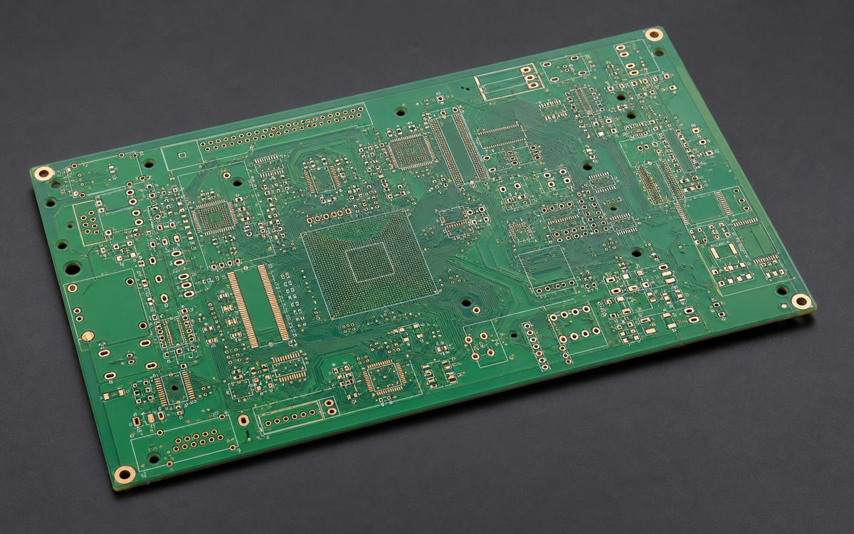
AER01 / PROJECT REQUIREMENTS
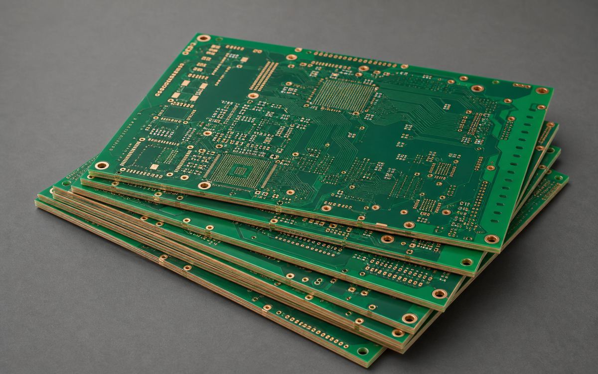
The PCB requirements for this PCBA project specified a four-layer immersion-silver board supplied in six-board panels. The customer specified breakaway connections, tooling rails and optical fiducials, with panel artwork approval required before production.
AER02 / PROJECT REQUIREMENTS
This four-layer FR-4 order required wide tooling rails for handling, tented vias and fiducials on both sides. The customer also required panel artwork approval and shipment documentation with production traceability.
AER03 / PROJECT REQUIREMENTS
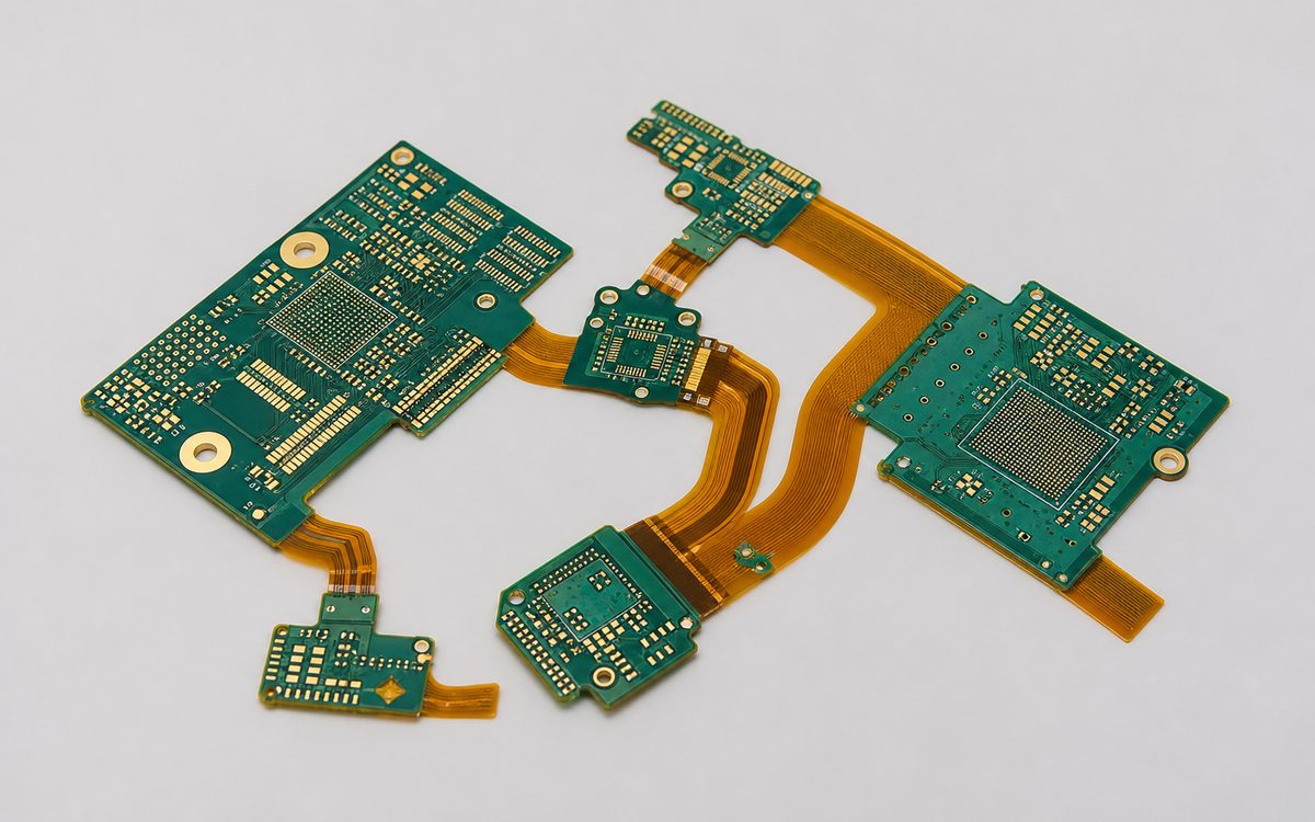
The PCB requirements for this PCBA project combined a thin six-layer FR-4 construction, blind vias, resin filling and L3 impedance control. The customer approved splitting the original L1–L5 blind-via connection into successive layer pairs with a 0.2 mm hole diameter.
For aerospace PCB and PCBA projects, supplier qualification should also consider material traceability, production and inspection records, and final release documentation relevant to your project.
Review Compliance EvidenceConfirm which certifications and quality systems apply to your project and manufacturing requirements.
Review approved sources, material records, lot/date code information, and authorized substitutions where required.
Review manufacturing, inspection, and test records linked to the production lot.
Confirm required test results, traceability records, and release documentation before shipment.
You do not need every answer before contacting EBest PCBA. Send the available files and identify the open questions; engineering will confirm missing inputs before quotation.
Explore practical guidance on PCB design, materials, inspection, traceability, and reliability requirements for aerospace electronics.
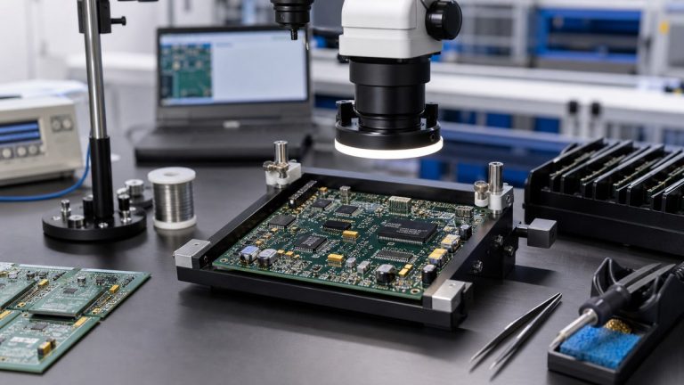
See how our MES-related records connect approved revisions, materials, production, inspection, testing and release evidence for aerospace PCBAs.
Read article →See how we control RF and impedance PCB stack-up, materials, geometry, coupons, testing and production records for aerospace projects.
See how we review PCB construction, solder joints, components and inspection evidence for aerospace PCBA thermal-cycling and vibration risks.
See how our engineers review laminate, copper, stack-up, thermal, RF and traceability requirements for high-reliability aerospace PCB production.
Review the certifications, engineering controls, inspection, testing and traceability evidence we provide for aerospace PCB and PCBA projects.
See how we convert an aerospace PCB or PCBA prototype into a controlled production build through engineering review, configuration control, inspection, testing and traceability.
Send the available design files, sourcing constraints, quantities and acceptance requirements. EBest PCBA will identify project fit, missing inputs and the next quote-ready step.