

01 / ROBOTICS ENGINEERING
Robotics PCB Layout & DFM
Review processors, sensors, motor-control interfaces, power domains, component placement, enclosure fit and test access before release.
Review robotics PCB layout →EBest PCBA supports PCB and PCBA projects for robotics and instrumentation, with DFM review, fabrication, component sourcing, assembly, programming, testing, and box build.
 Robotics Electronics Application
Connect robotics PCB layout, controller PCB prototyping, high-mix production, programming, test and mechanical integration for machine vision, motion control and precision instruments.
Review processors, sensors, motor-control interfaces, power domains, component placement, enclosure fit and test access before release.
Review robotics PCB layout →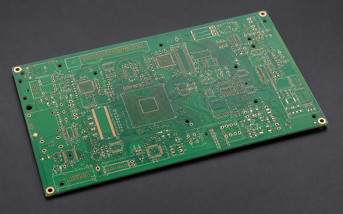
Confirm stack-up, impedance, sensor and motion interfaces, component availability, assembly fit and open NPI questions before repeat builds.
Review controller PCB prototypes →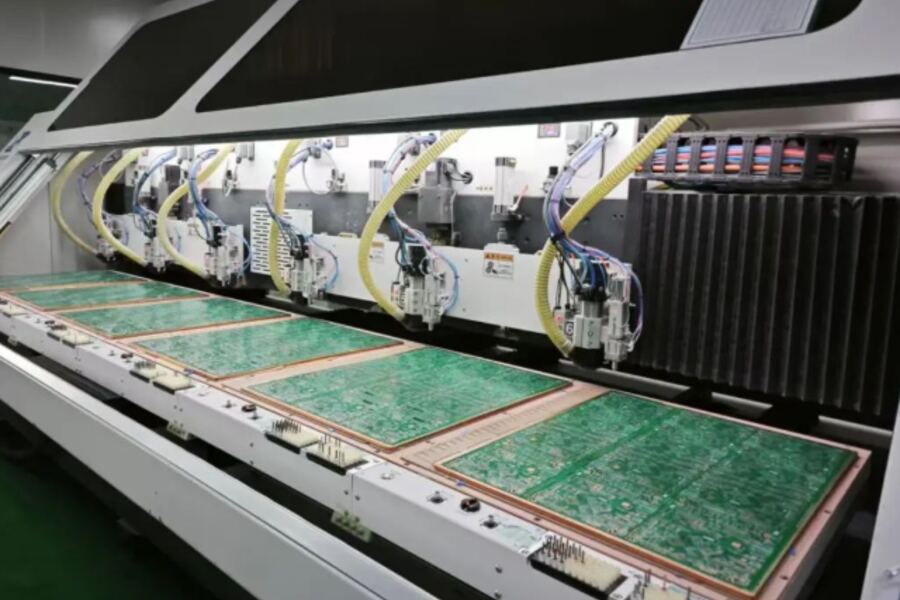
Release approved materials, fabrication data, BOM controls, stencil, reflow, inspection and traceability requirements across controlled product variants.
Review high-mix PCBA production →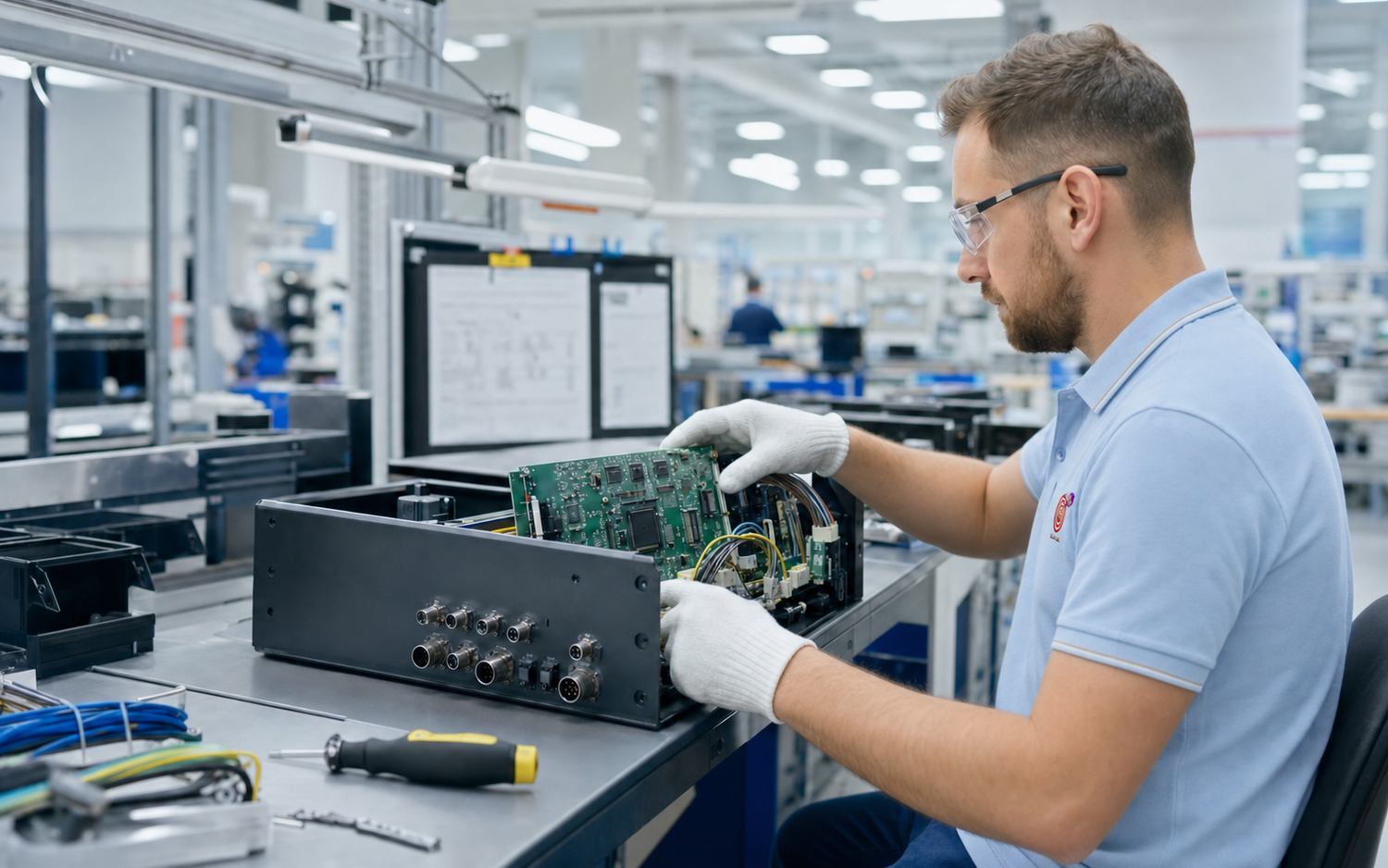
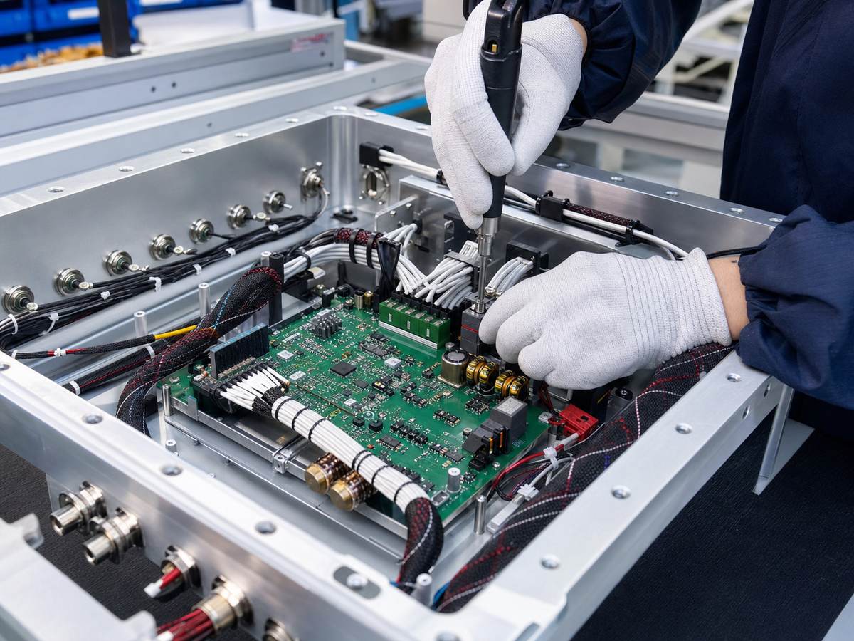
Connect released robotics PCBA, firmware, cable harnesses, enclosure integration and project-defined motion or functional acceptance.
Review robotics box build →Robotics electronics must reliably handle power, motion, sensors, communication, mechanical integration, and software-controlled functions. Reviewing these requirements before production helps identify issues that PCB DFM alone may not cover.
Link approved manufacturers, alternates, availability, variants and customer authorization to each released build.
Review reference planes, impedance, grounding, analog and digital separation, interfaces and test access from the actual design.
Coordinate switching paths, copper, thermal transfer, motor interfaces and assembly conditions before fabrication.
Confirm board outline, connectors, cable exits, mounting, height restrictions and enclosure interfaces against released drawings.
Define firmware ownership, SPI, AOI, X-ray, electrical or functional coverage, limits, fixtures and required records.
These application scenes identify common project contexts; they are not customer-project claims. Final construction, integration and test coverage follow the released files.
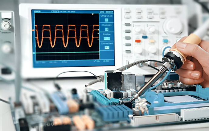
Low-noise acquisition, signal conditioning, interfaces, shielding and repeatable functional acceptance shape the build route.

Motion control, safety I/O, sensors, communications, motor interfaces and cable integration require coordinated review.
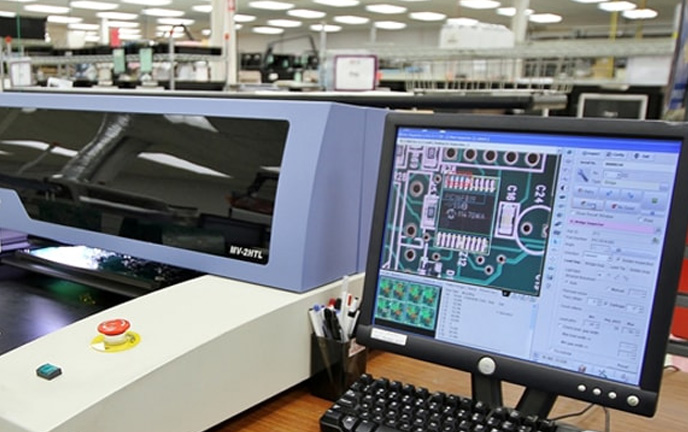
High-speed processors, cameras, lighting, data interfaces, thermal control and mechanical alignment must work together.
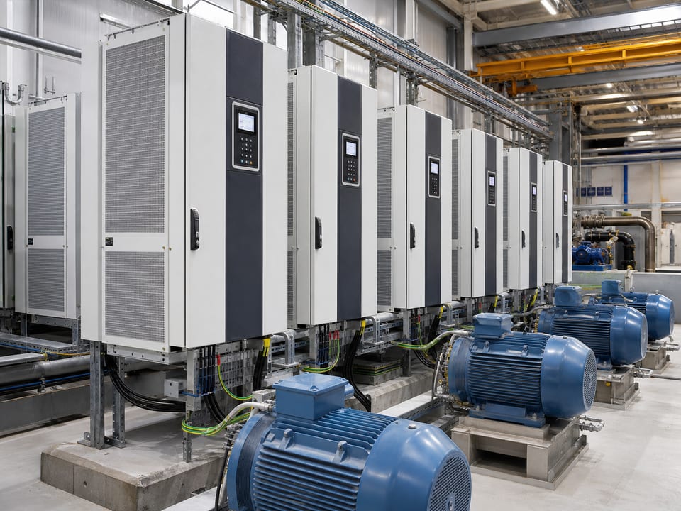
Gate drive, current sensing, feedback, isolation, switching noise and power-stage heat determine layout and verification priorities.
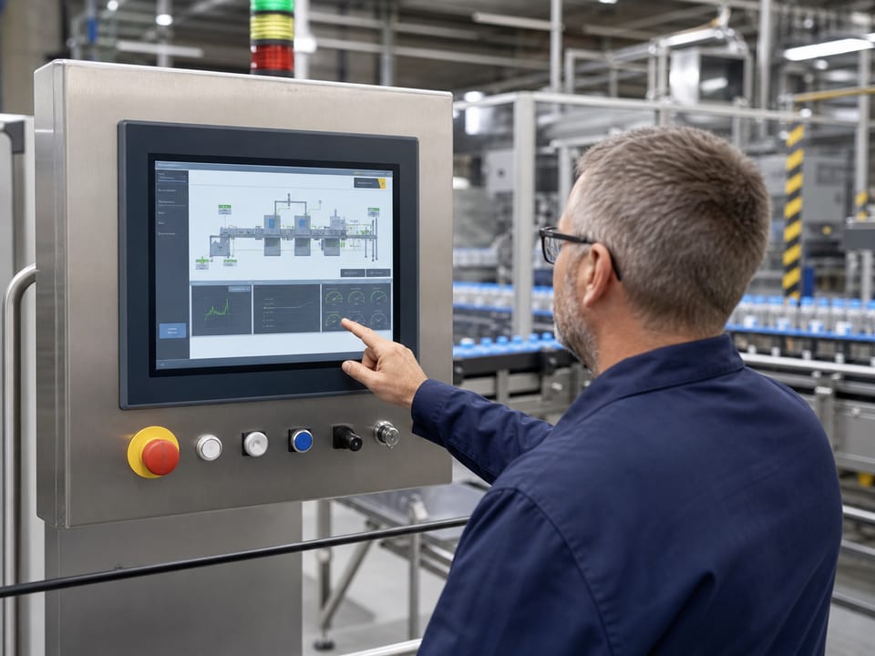
Display, control, acquisition, communications and enclosure constraints require an approved hardware and test configuration.
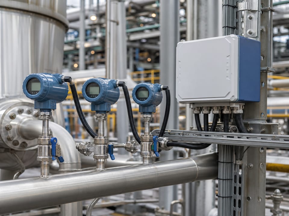
Analog integrity, grounding, calibration interfaces, environmental exposure and data communication must be reviewed together.
Send your approved files and requirements. EBest PCBA confirms the PCB layout, manufacturing, assembly, testing and box-build scope before quotation.
| Review Area | You Provide | EBest PCBA Confirms |
|---|---|---|
| Project Files | Gerber, BOM and drawings | File completeness and scope |
| PCB Layout | Schematic, stack-up and layout rules | Layout scope and implementation |
| Components | Approved BOM and alternatives | Availability and sourcing |
| Assembly | Assembly drawings and requirements | Assembly process |
| Inspection & Test | Inspection and test requirements | Coverage and records |
| Box Build | Enclosure and cable drawings | Integration scope |
Each stage confirms the electrical, mechanical, sourcing, assembly, programming, inspection, and test requirements needed before the project moves into production.
Confirm available PCB files, BOM, drawings, quantities, interfaces, mechanical constraints, and other project information.
Review PCB construction, stack-up, components, power, signals, connectors, programming, and manufacturability risks.
Build and review prototype or pilot units to confirm assembly, mechanical fit, programming, inspection, and test readiness.
Manufacture and assemble against approved files, BOM revisions, materials, and defined process requirements.
Apply required programming, SPI, AOI, X-Ray, electrical testing, functional testing, and acceptance criteria.
Link approved revisions, material records, inspection results, test data, and traceability information to the finished production lot.
Explore PCB and PCBA manufacturing routes for instruments, motion control and robotics. Final specifications follow review of your released data.
A coordinated control-board route for processors, feedback, communication and motor-control interfaces.
Review multilayer capability →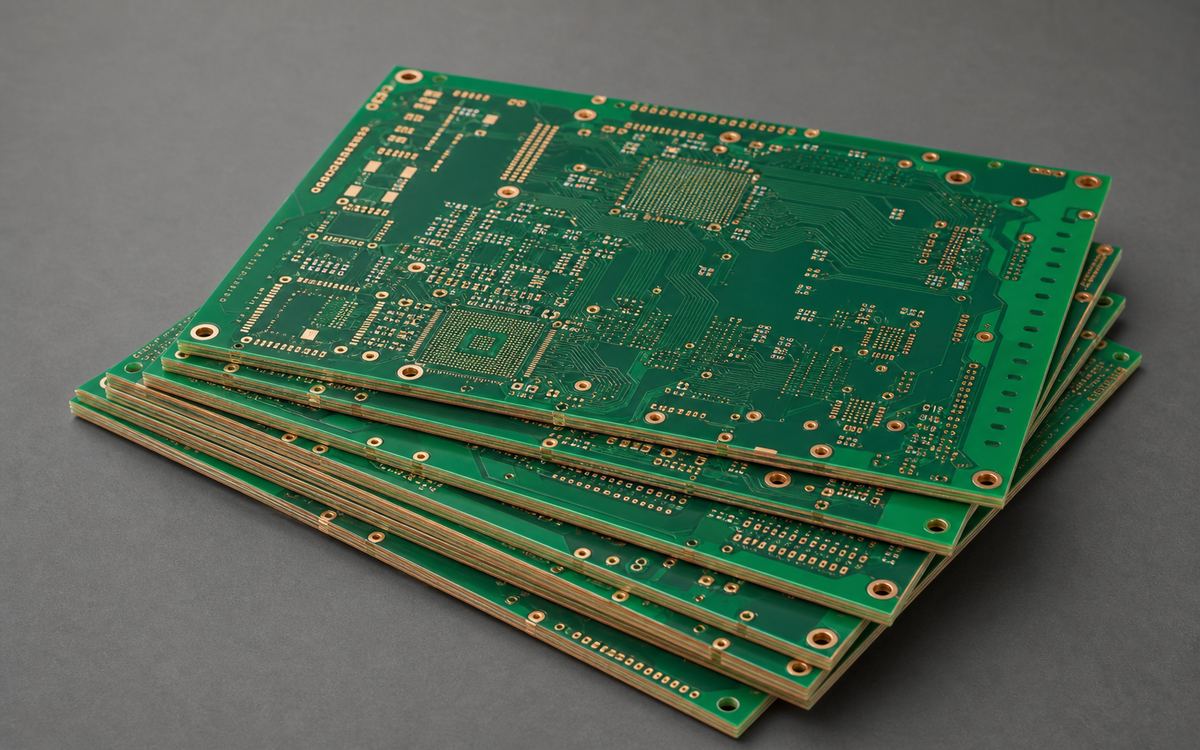
A stack-up-led route for processors, high-speed data, camera or network interfaces and reference-plane control.
Review PCB manufacturing →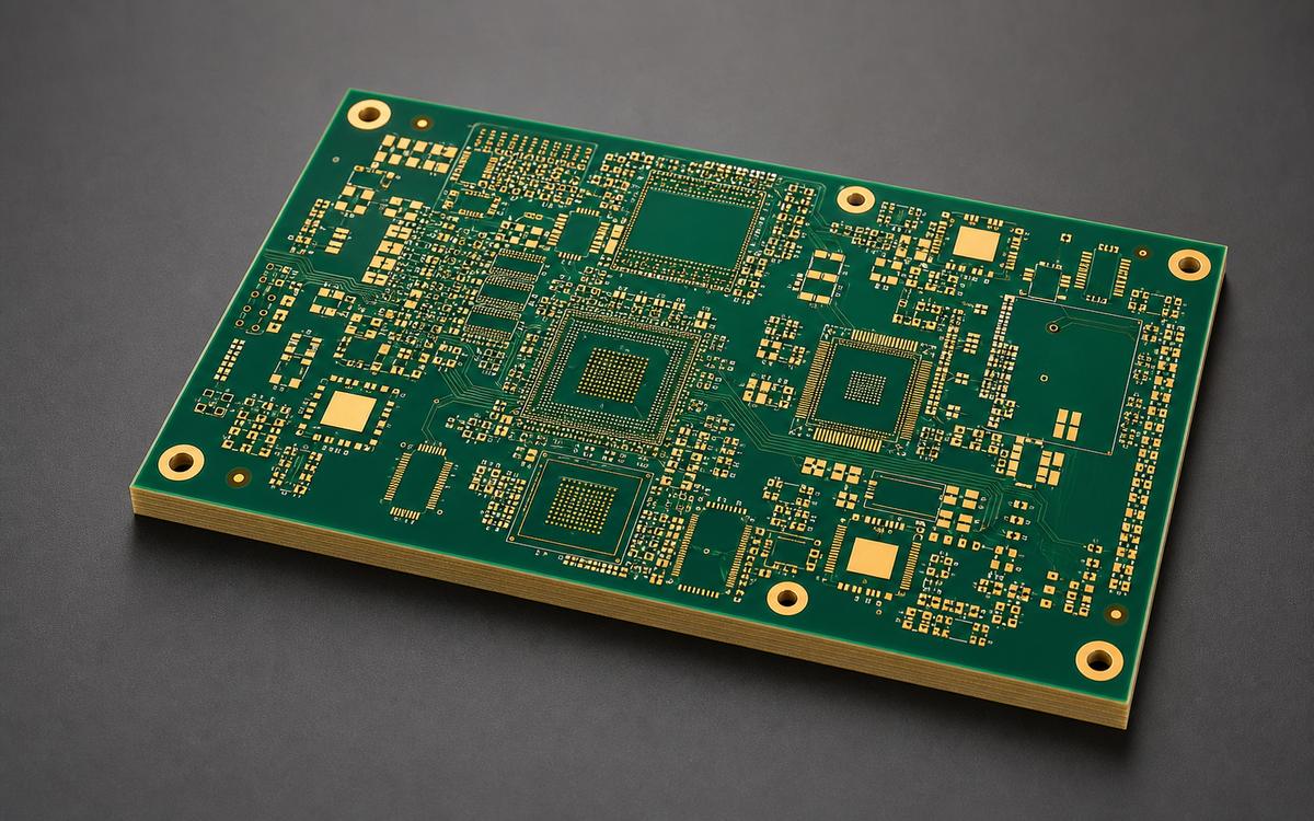
A thermal-cycle-aware multilayer route for drive and control electronics exposed to sustained heat.
Review FR-4 capability →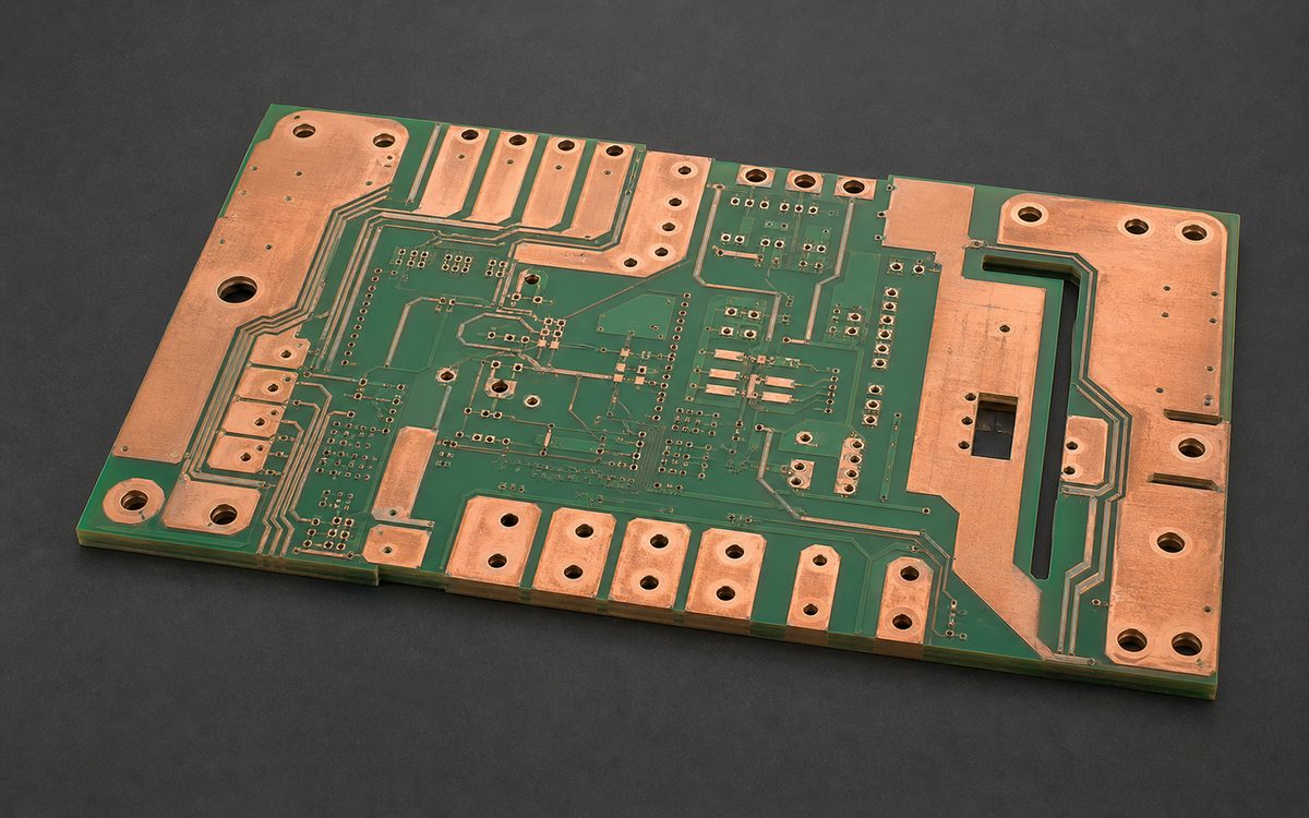
A power route where current, copper distribution, plated holes, spacing and heat must be reviewed together.
Review this PCB route →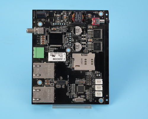
An assembled route connecting approved components, mixed packages, inspection access, programming and project-defined test.
Review PCBA assembly →A finished-product route linking PCBA, cables, enclosure, firmware, labels and project-defined functional test.
Review box-build services →Before choosing a manufacturing partner, review the DFM process, PCB/PCBA capabilities, inspection and testing equipment, and quality certifications relevant to your project.
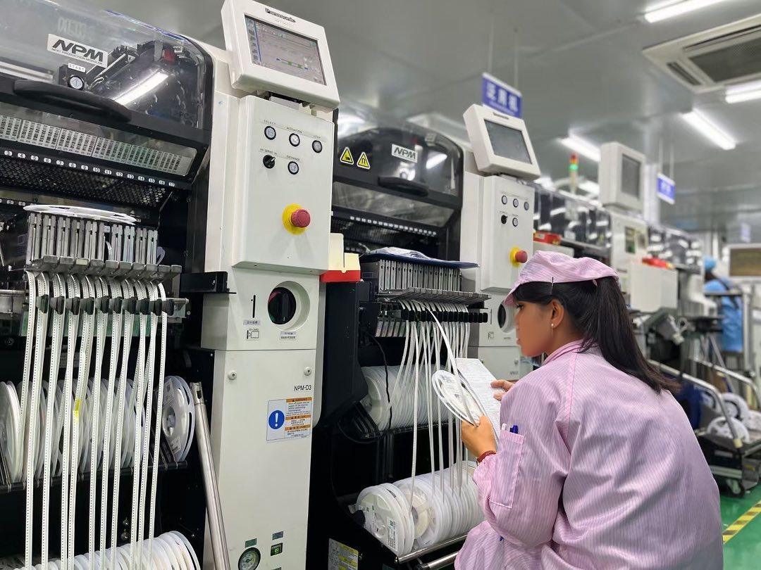
You do not need every answer before contacting EBest PCBA. Send the available files and flag the open questions; engineering will identify missing inputs before quotation.
Review practical guidance on manufacturability, signal integrity, component sourcing, assembly, inspection, and testing for precision control and instrumentation projects.
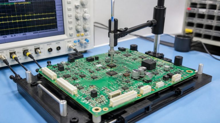
See how we inspect and test robotics PCBAs across solder process, hidden joints, programming, sensors, communications and motor-control functions.
Read article →See how we manufacture rigid-flex PCBs for moving robotics interconnects with controlled materials, bend zones, transitions, stiffeners and inspection.
See how we preserve machine-vision PCB stack-up, impedance, materials, vias, connectors and inspection requirements through manufacturing.
See how we review and manufacture motor-drive PCBs with controlled copper, vias, power joints, thermal interfaces, inspection and testing.
See how our engineers review robotics control PCB layout, stack-up, power, sensors, communication, connectors and test access before manufacturing.
See how we convert robotics PCB and PCBA prototypes into controlled production through engineering release, sourcing, inspection, testing and traceability.
Share the files and requirements you already have. EBest PCBA will review the PCB construction, component sourcing, assembly, mechanical integration, inspection, and test requirements before the project moves forward.