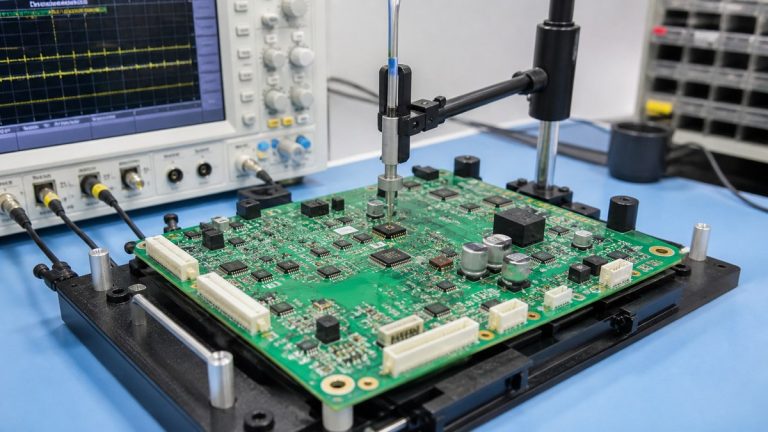
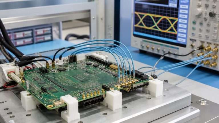
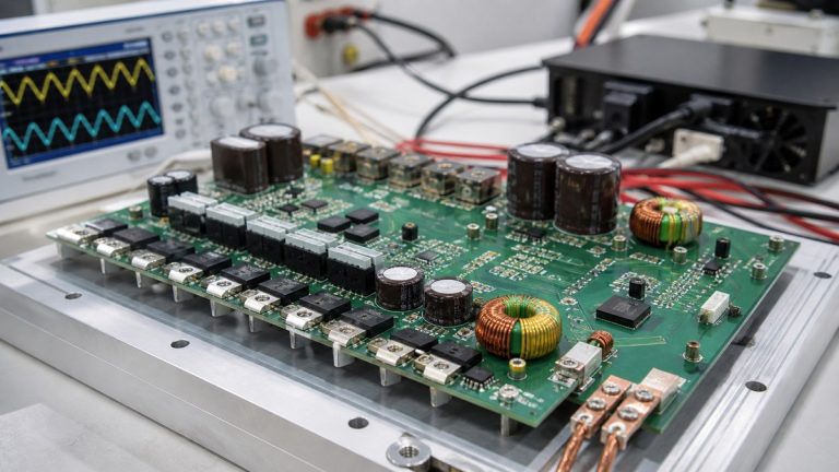
We manufacture rigid-flex PCBs from an approved regional construction that separates rigid circuitry, flexible interconnects, transition zones, stiffeners and component areas. For robotics projects, our engineers review whether the flex is installed once or moves repeatedly, then connect that condition to material, copper, bend geometry, tooling and inspection.
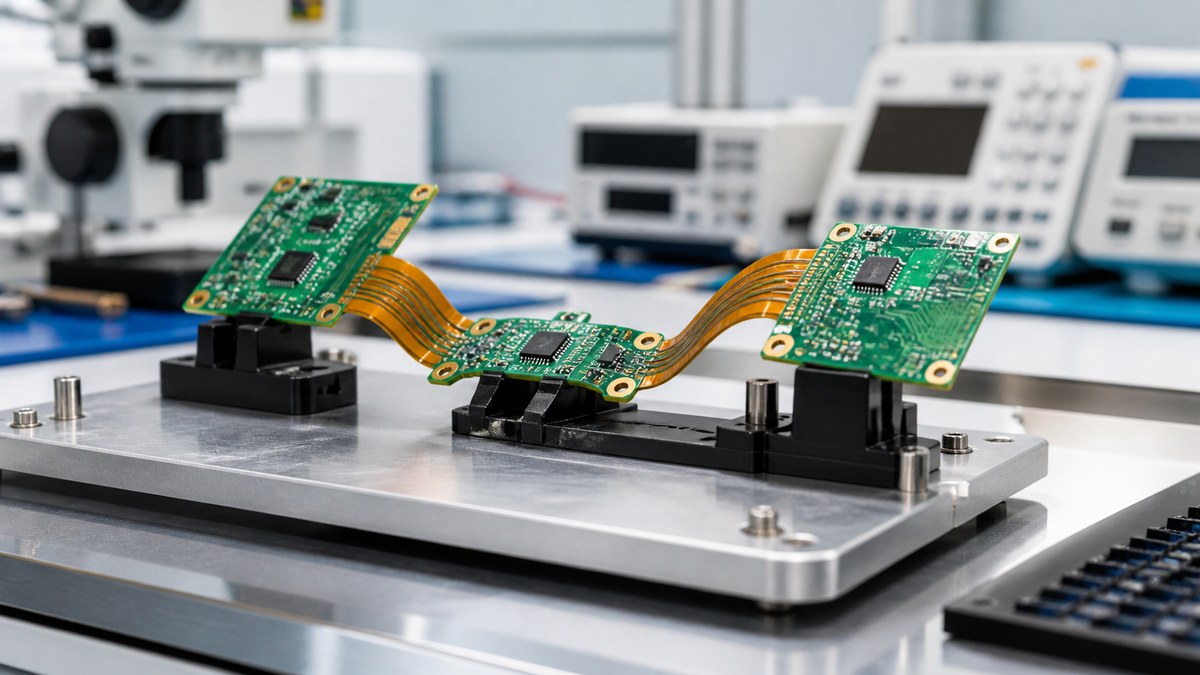
You receive a released rigid-flex stack-up, manufacturing questions and evidence for the buildable features. Product bend life remains validated under your actual motion, radius, speed and environment; our role is to manufacture the approved construction without introducing uncontrolled stress.
Rigid-Flex Manufacturing Decision Map
| Design input | Our control | Evidence |
|---|---|---|
| Static or dynamic use | Separate installation bend from repeated motion | Approved bend condition in released data |
| Material system | Control rigid laminate, flex dielectric, copper, coverlay and adhesive | Released stack-up and material identity |
| Bend zone | Review radius, layer count, copper direction and keep-outs | Manufacturing-risk response |
| Rigid-flex transition | Control coverlay, adhesive, copper and mechanical geometry | Applicable inspection evidence |
| Connector or stiffener | Review location, thickness, adhesive and assembly load | Controlled drawing and assembly instruction |
We Need the Real Motion Condition
We ask whether the flex is bent during installation, moves occasionally or cycles continuously. Required bend radius, angle, cycle count, speed, temperature, torsion and cable restraint affect the approved design.
Calling every flex “dynamic” does not define the product. Your team supplies the motion and life requirement; we use it to review manufacturability and protect the specified bend region.
We Release a Regional Material Construction
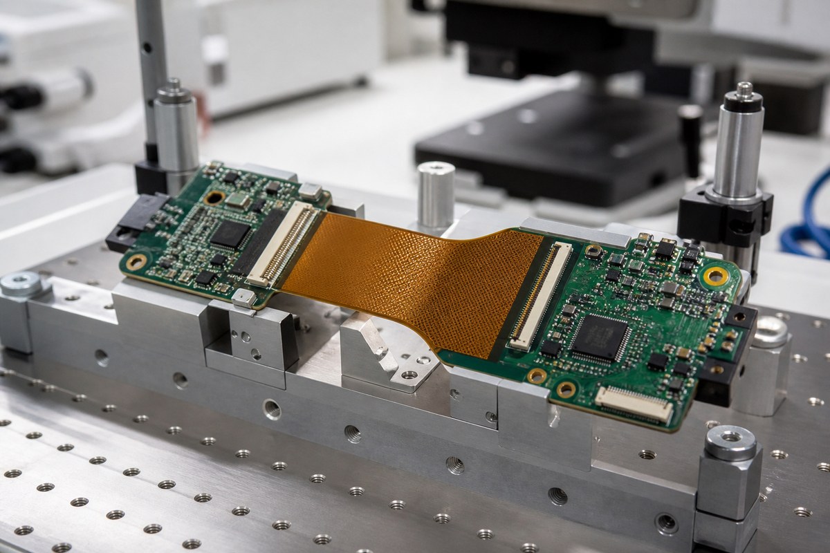
Rigid-flex combines rigid laminate, polyimide, copper, coverlay, adhesive and stiffeners in different board regions. We review layer transitions, dielectric thickness, copper type and thickness, bonding and assembly heat exposure.
The approved material system remains tied to the stack-up. A substitution is reviewed for mechanical, electrical and process effects before use.
Bend Zones Stay Free From Uncontrolled Features
We review traces, planes, vias, pads, coverlay openings, component keep-outs and rigid hardware around the bend zone. Copper direction and width transitions should match the approved mechanical design.
Panel tooling and handling instructions prevent production from folding or clamping the flex in an unintended location.
Rigid-to-Flex Transitions Receive Focused Control
Transitions can concentrate stress where material thickness and stiffness change. We review geometry, copper routing, coverlay termination, adhesive and any specified strain-relief feature.
Applicable visual, dimensional or structural evidence is planned for representative conditions. The exact product-life result still depends on the customer’s installed motion.
Stiffeners and Connectors Need Mechanical Agreement
We check stiffener material, thickness, adhesive, location, connector contact area, tolerance and insertion load. A stiffener that is shifted or too thick can prevent connector fit even when the electrical circuit is correct.
Approved dimensions and assembly sequence become controlled instructions and inspection points.
Assembly Tooling Protects Flexible Areas
We review panelization, carriers, component placement, soldering support and depanelization so flexible regions do not sag, twist or receive uncontrolled heat and handling.
SPI, AOI and X-ray can be used for applicable assembly risks, while flex-region inspection checks the conditions defined by the drawing and work instruction.
Testing Separates Connectivity From Bend Life
Bare-board electrical test verifies specified continuity and isolation. PCBA functional testing verifies defined electronic behavior. Neither automatically proves the required number of mechanical bend cycles.
When bend testing or external qualification is required, the condition, fixture, sample quantity, acceptance rule and evidence are defined separately and connected to the tested revision.
Why Robotics Customers Use Our Rigid-Flex Process
We keep material, bend zone, transition, stiffener, tooling and inspection decisions connected to one build. Your team can see how the moving interconnect design enters production and which manufacturing evidence supports it.
This reduces assembly damage and uncontrolled construction changes between robot builds.
Send Your Rigid-Flex Motion Requirements
Send Gerber or ODB++, stack-up, rigid-flex drawing, material callouts, static or dynamic condition, bend radius, cycle target, mechanical data, stiffener and connector requirements, assembly files, quantities and required qualification evidence to sales@ebestpcba.com.
We will return the construction questions, proposed manufacturing controls and evidence plan.