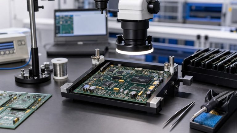
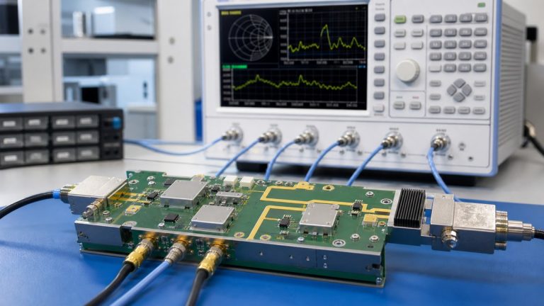
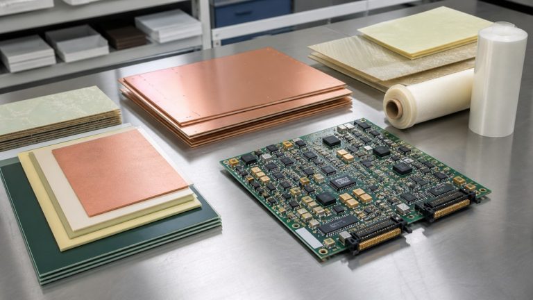
We help aerospace customers convert thermal-cycling and vibration requirements into manufacturable PCB and PCBA controls. Our engineers review the complete assembly—not only the laminate—because failures can develop in plated holes, microvias, solder joints, component terminations, connectors, heavy parts, rigid-flex transitions and mechanical interfaces.
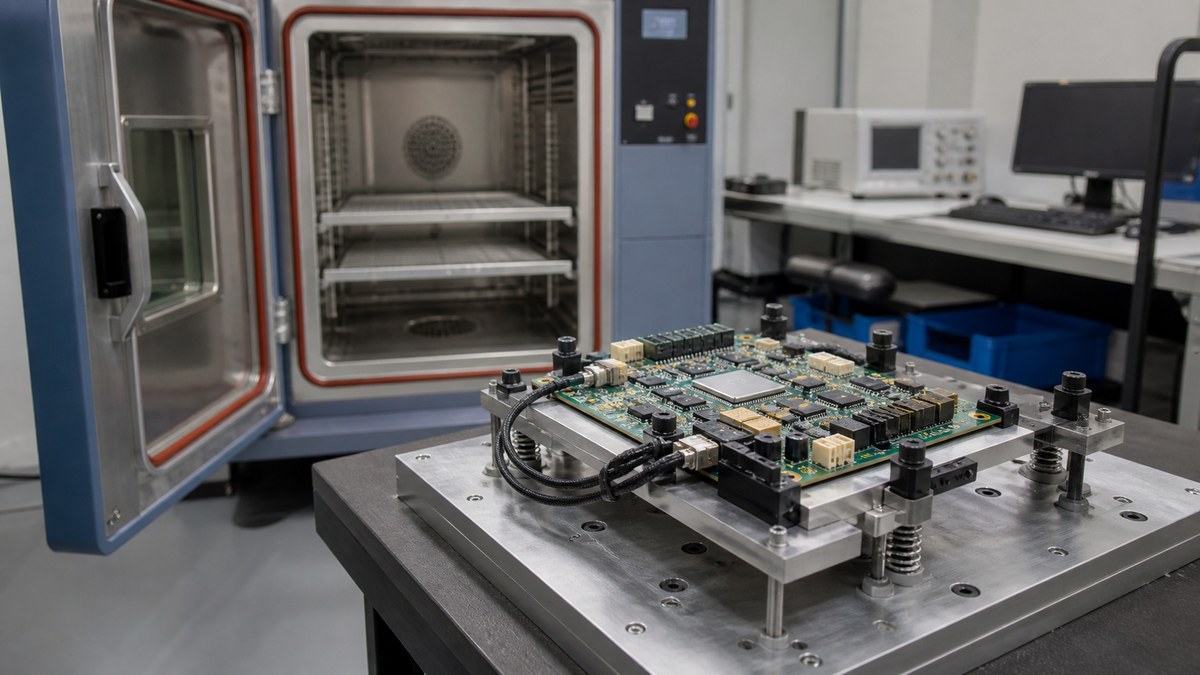
You receive an engineering risk review connected to the approved construction, manufacturing route, inspection plan and required qualification evidence. We do not claim that a material grade or a successful prototype proves reliability under every mission profile. We identify the features influenced by manufacturing and show how we will control and document them.
What We Need to Control the Real Stress Risk
| Stress concern | What we review and control | Evidence for your team |
|---|---|---|
| Thermal expansion | Material system, board thickness, copper and via construction | Approved stack-up and applicable structural evidence |
| Solder-joint fatigue | Package, pad, paste, thermal mass and assembly profile | Process, inspection and qualification records as agreed |
| Vibration loading | Heavy parts, connectors, support, board outline and fasteners | Manufacturing review and controlled assembly instructions |
| Rigid-flex movement | Bend zone, transition, stiffener and installation condition | Released construction and inspection points |
| Qualification failure | Built revision, material identity, process history and affected feature | Traceable evidence for failure review |
We Review Your Actual Thermal and Vibration Profile
Our review starts with operating and storage temperatures, ramp rate, dwell time, cycle count, vibration spectrum, acceleration, mounting condition, enclosure interface and combined loads. These inputs determine which PCB and PCBA features need attention. A generic “aerospace environment” description is not enough to release a useful manufacturing plan.
We separate customer design authority from our manufacturing responsibility. Your team defines the system environment and qualification requirement. We confirm whether the released construction can be fabricated, assembled, inspected and traced as intended, and we identify missing data before production.
PCB Material and Via Construction Are Reviewed Together
We assess laminate and prepreg together with CTE, board thickness, copper distribution, plated-hole aspect ratio, microvia structure and assembly heat exposure. The material datasheet alone cannot show how the completed via system will respond to repeated expansion and contraction.
For sequential lamination, stacked microvias, heavy copper or high layer counts, we define the applicable process and structural evidence before release. The approved stack-up, drill structure and material callout remain tied to the same product revision.
We Control Assembly Features That Carry Mechanical Load
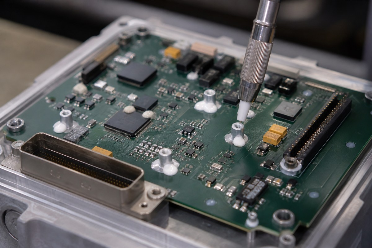
Large components, transformers, inductors, connectors, heat sinks and cable interfaces can transfer vibration into solder joints and the PCB. Our assembly review checks placement, support, lead condition, hardware, adhesive or staking requirements, keep-outs and access for inspection.
When a support method is specified, we turn it into controlled material, location, application and acceptance instructions. This gives your team evidence that the production assembly uses the same mechanical-control decision approved during qualification.
Soldering Controls Support Thermal-Fatigue Reliability
We review pad and paste geometry, package thermal mass, component terminations, board copper distribution and the planned soldering route. A joint that appears acceptable after one build can still be sensitive to voiding, insufficient solder, excessive solder or uneven heating.
SPI, AOI and X-ray are assigned according to the joint structure. SPI supports solder-paste control, AOI covers applicable visible conditions and X-ray provides evidence for selected hidden joints. We define coverage and acceptance criteria before production rather than treating equipment names as a reliability claim.
Rigid-Flex Areas Receive Their Own Review
For rigid-flex PCBAs, we identify static and dynamic bend conditions, bend radius, layer construction, copper direction, coverlay, stiffeners, rigid-to-flex transitions and installation restraints. Assembly tooling and handling must protect flex regions from uncontrolled bending.
The released drawing and work instructions identify the bend and no-bend areas relevant to manufacturing. Product-life validation remains tied to the customer’s defined motion and qualification conditions.
Qualification Results Stay Connected to the Built Configuration
When thermal-cycle or vibration testing is part of the program, the result is meaningful only when the test unit can be connected to its design revision, materials, components and manufacturing history. Our work-order and available MES-related records support that connection within the agreed traceability depth.
If a failure occurs, we help separate the affected feature, built condition and available process evidence. Microsection, X-ray, electrical test, visual inspection or external analysis may answer different questions. The investigation method is selected for the suspected failure mechanism.
Why Customers Use Our Reliability Manufacturing Review
We turn environmental requirements into specific manufacturing decisions instead of adding broad “high-reliability” labels. Your team can see which construction and assembly features we reviewed, how they enter the controlled route and what evidence will be available.
This approach reduces the risk of qualifying one prototype condition and then changing material, support, soldering or inspection details during repeat production without a new decision.
Send Your Thermal and Vibration Requirements
Send your Gerber or ODB++ data, stack-up, BOM, CPL, assembly drawing, enclosure and mounting information, operating and storage temperatures, thermal-cycle profile, vibration spectrum, qualification standard, inspection needs and required reports to sales@ebestpcba.com.
We will return the manufacturing risks, proposed controls, evidence plan and questions that must be resolved before the aerospace PCB or PCBA is released.