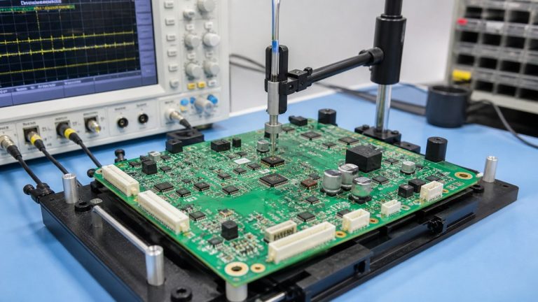
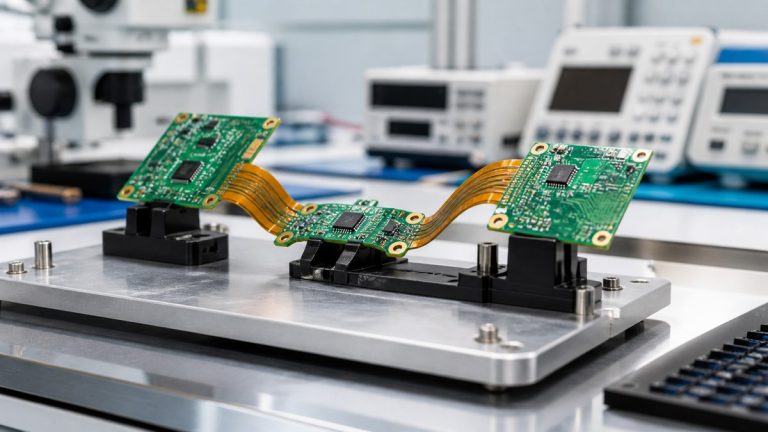
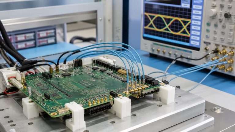
We review robotics control PCBs for fabrication, assembly, inspection and test before release. Our engineers focus on the interfaces where manufacturing details can change system behavior: motor power, sensor inputs, high-speed communication, grounding, connectors, mechanical mounting and firmware test access.
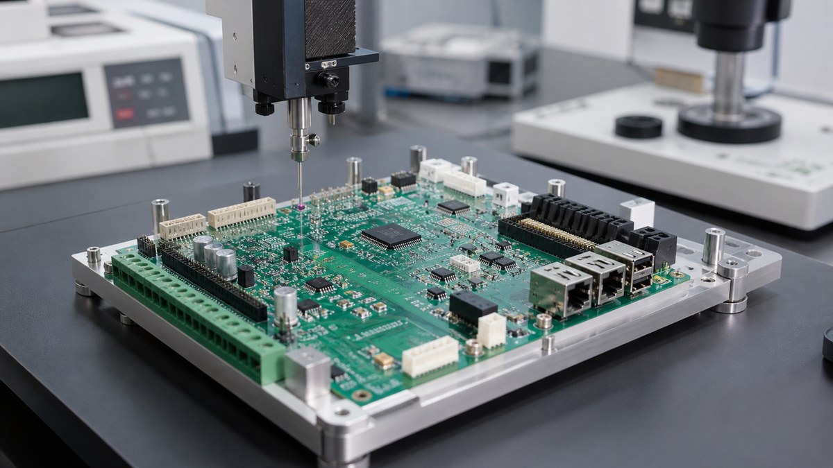
You receive specific DFM questions, an approved manufacturing construction and a proposed evidence route. We preserve your electrical design authority while identifying layout details that may be difficult to build, inspect or repeat.
Robotics PCB Review Checklist
| Area | What we check | Output |
|---|---|---|
| Data package | Revision agreement across PCB, BOM, CPL and drawings | Controlled release list |
| Power and motor control | Copper, vias, thermal pads, isolation and connectors | Manufacturing-risk questions |
| Sensors and communication | Stack-up, reference planes, differential structures and launches | Buildable construction |
| Assembly access | Land patterns, polarity, spacing, tooling and rework access | Assembly DFM response |
| Inspection and test | Hidden joints, test points, programming and fixtures | Coverage proposal |
We Confirm That Every File Describes One Robot Revision
We compare Gerber or ODB++, drill data, stack-up, fabrication drawing, BOM, CPL, assembly drawing and mechanical data. Processor, driver, sensor, encoder and connector identities and orientations must agree.
Conflicts are returned before CAM and placement programming. Approved answers remain tied to the work order.
Power and Motor-Drive Areas Need Manufacturable Current Paths
We review layer-specific copper, trace and plane geometry, via arrays, exposed pads, high-current terminals and heat-sink interfaces. Copper weight and finished thickness must be stated consistently across the package.
We identify features affected by etching, plating, soldering or inspection. Current capacity and operating temperature remain verified by the customer under representative system conditions.
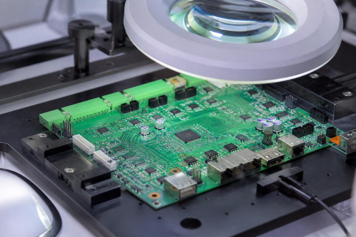
Sensor Inputs Need Quiet Physical Implementation
For analog and low-level sensor sections, we review manufacturability around reference planes, return paths, separation, connector entry and grounding features defined by the design. We look for splits, voids or ambiguous layer relationships that production data could interpret incorrectly.
We do not redesign the sensing circuit. We ensure the approved physical relationships survive stack-up and fabrication release.
High-Speed Communication Depends on the Final Stack-Up
For Ethernet, USB, camera or other controlled structures, we connect the target impedance to material, dielectric thickness, copper, trace geometry and reference plane. Proposed geometry adjustments return for approval.
Where required, representative coupons and impedance reports remain tied to the production construction. Connector launches and layer transitions receive separate manufacturing review.
Connectors and Mechanics Must Match the Robot Assembly
We check board outline, mounting holes, edge connectors, cable direction, component height, enclosure keep-outs and insertion-force support. A connector can be electrically correct but impossible to access or mechanically unsupported.
Mechanical data and assembly sequence allow us to identify these conflicts before tooling.
We Plan Inspection for Hidden and Visible Risks
SPI covers applicable paste-printing conditions, AOI covers visible placement and joints, and X-ray supports selected hidden packages. We also review whether shields, heat sinks or connectors block later inspection.
The approved plan states coverage and output so your team can see how manufacturing risk will be verified.
Test Access Is Reviewed Before Layout Becomes Fixed
We check programming headers, boundary access, power rails, communication ports, fixtures and required test points. ICT, flying probe and FCT need different access and data.
Early review protects the test strategy from discovering after fabrication that critical nodes or interfaces cannot be reached.
Why Robotics Teams Use Our Layout Review
We connect the robot’s power, sensing, communication and mechanical interfaces to a controlled manufacturing route. Your team receives actionable questions instead of a generic DFM score.
This reduces file conflict, assembly access, inspection and test surprises before the first controlled build.
Send Your Robotics Control Board for DFM
Send product files, stack-up, BOM, CPL, assembly and mechanical drawings, impedance requirements, current and thermal information, connector data, programming files, test procedure and quantities to sales@ebestpcba.com.
We will return the manufacturing questions, proposed construction and inspection or test evidence route.