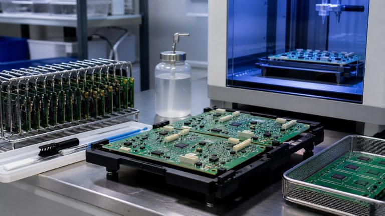
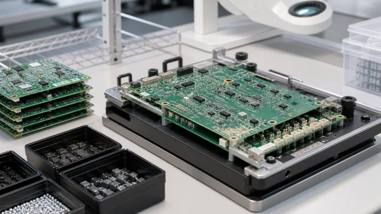
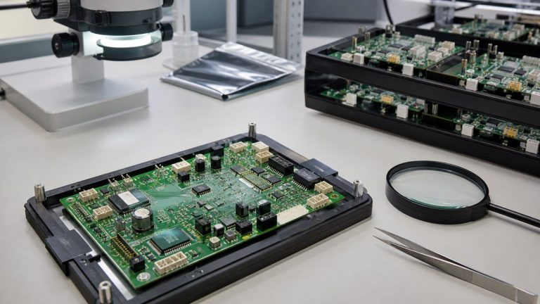
We use AOI, X-ray, ICT and functional testing for different medical PCBA risks. Our engineers select the combination from the released assembly, package mix, test access, defined functions and customer acceptance criteria. No single method proves the complete product.
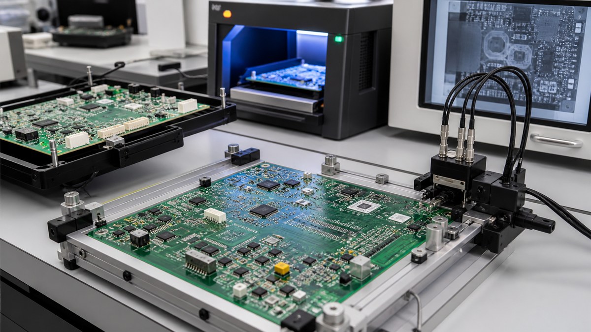
You receive a coverage plan and product-linked results that show what each method checked, which program or procedure revision applied, the outcome and disposition. This supports manufacturing release while keeping medical-device validation separate from the defined PCBA test scope.
Inspection and Test Comparison
| Method | What we use it for | What the evidence does not prove |
|---|---|---|
| AOI | Visible placement, polarity and solder conditions | Hidden joints or electrical function |
| X-ray | Selected BGA, QFN and hidden interconnects | Every solder defect or powered behavior |
| ICT | Accessible connectivity and component conditions | Complete system function |
| FCT | Specified powered inputs, outputs and interfaces | Unspecified clinical, safety or lifetime performance |
We Start With the Failure Question
Our review identifies polarity-sensitive parts, fine-pitch printing, hidden joints, high-current or high-voltage sections, programmed devices, analog channels, communication interfaces and critical functions.
Each risk is assigned prevention, inspection or test coverage. If an important condition has no practical coverage, we raise the gap before production.
AOI Checks Visible Assembly Conditions
AOI can identify applicable missing, shifted or wrong components, polarity conditions and visible solder anomalies. The program is prepared for the released product and evaluated against the approved workmanship basis.
Results and dispositions remain connected to the lot or work order. AOI is not used to claim coverage of hidden connections.
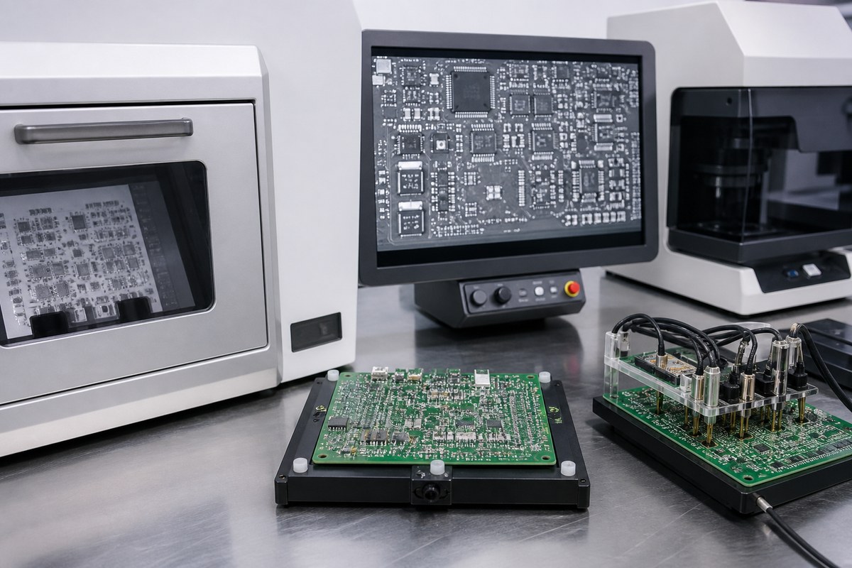
X-ray Supports Hidden-Joint Evidence
We use X-ray for selected bottom-terminated packages and other structures that optical inspection cannot see. The plan defines locations, sampling or unit coverage, acceptance and required images.
X-ray interpretation is connected to the specified risk. We combine it with process inspection and electrical testing where those methods answer different questions.
ICT Requires Access and a Defined Program
ICT can verify applicable connectivity and component conditions when the design provides test access and the fixture or probe strategy supports the assembly. We review test points, isolation, fixture ownership, program revision and limits.
The record identifies the tested product, program and result. A passed ICT does not prove every powered function or medical-device requirement.
FCT Verifies the Functions the Customer Defines
FCT may check power rails, analog channels, sensors, communication, controls or other specified behavior. We require the procedure, firmware, fixture, input conditions, expected outputs and limits.
The report states which functions were tested. Clinical performance, safety and environmental qualification remain outside this evidence unless specifically defined and assigned.
Programming and Test Revisions Stay Controlled
We connect approved firmware, programming and test files to the product revision. Hardware or software changes receive review for fixture, program and acceptance compatibility.
This prevents an obsolete test program from producing apparently valid results for a changed assembly.
Failures and Repairs Remain Visible
Failed units are contained and connected to diagnosis, approved repair or rework, retest and final disposition. Available work-order or serial-number links support retrieval.
Your team can review both initial failure and final status where the agreed evidence package includes that history.
Why Medical Customers Use Our Coverage Plan
We explain what each method can and cannot prove, then connect the applicable results to the released product. This avoids duplicate testing, uncovered risks and false confidence from an equipment list.
Your quality team receives manufacturing evidence that can support supplier control and product records.
Send Your Medical PCBA Test Requirements
Send product files, BOM, CPL, assembly drawing, package list, workmanship criteria, test points, firmware, fixture information, procedure, limits, quantities, sampling and report format to sales@ebestpcba.com.
We will return the proposed AOI, X-ray, ICT and FCT coverage, missing inputs and evidence available.
How We Build the Inspection and Test Plan With You
Send us the assembly data, critical component list, acceptance standard, test specification and required records. We will map visible solder joints to AOI, hidden joints to X-ray where applicable, accessible nets to ICT and product functions to an approved FCT procedure. You can then approve a project-specific plan rather than paying for methods that do not address the actual risk.