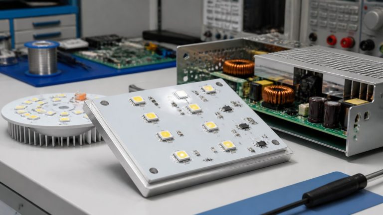
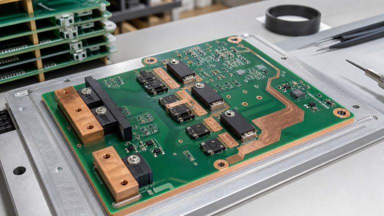
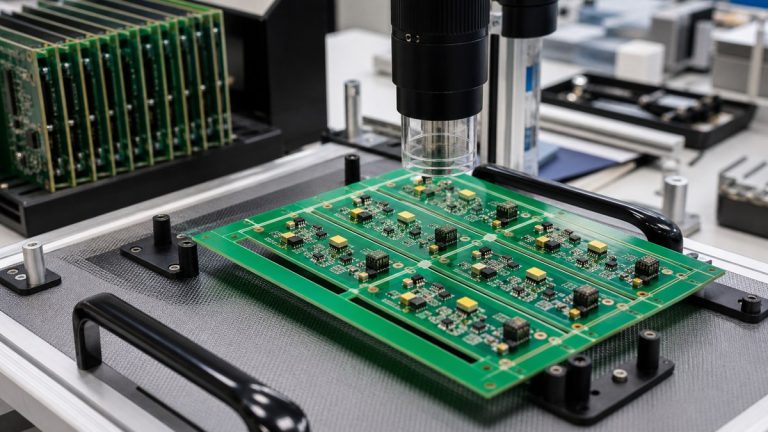
We inspect and test BMS and new-energy PCBAs with coverage designed around cell sensing, current measurement, isolation, communication, balancing, power control, connectors and programmed devices. We combine applicable process inspection, structural inspection, electrical checks and customer-defined functional testing.
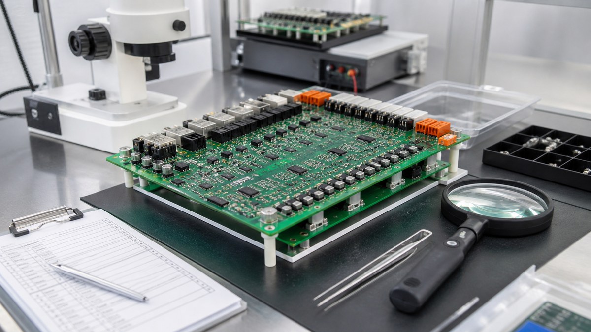
You receive results tied to the released hardware, firmware, method and limits. We state what each record proves and keep pack-level safety, calibration and validation separate unless those functions are explicitly included in the approved PCBA test.
BMS Inspection and Test Matrix
| Risk | Our method | Evidence |
|---|---|---|
| Paste or visible assembly defect | SPI, AOI and visual inspection where applicable | Process result and disposition |
| Hidden power or BGA joint | Selected X-ray | Applicable image or result |
| Wrong component or firmware | BOM control, first article and programming control | Released identity and programming result |
| Sensing or communication fault | Defined electrical or functional test | Procedure, limits and result |
| Isolation concern | Specified geometry, electrical or dielectric test | Applicable inspection or test record |
| Repair history | Controlled failure, rework and retest path | Final disposition linked to the unit or lot |
We Begin With the BMS Risk and Interface Map
Our engineers review cell inputs, current-sense paths, temperature channels, balancing circuits, communication, contactor or power-control outputs, isolation boundaries and firmware. We also identify fine-pitch, hidden-joint and high-current assembly risks.
Each condition receives a defined manufacturing control or test. Gaps are returned before production rather than hidden behind a final power-on check.
First-Article and Process Inspection Protect Setup
First-article verification checks released revision, component identity, polarity, placement and programming basis. SPI controls applicable solder-paste conditions, and AOI checks visible assembly features.
Reaction rules identify how affected panels or units are contained and rechecked when a condition fails.
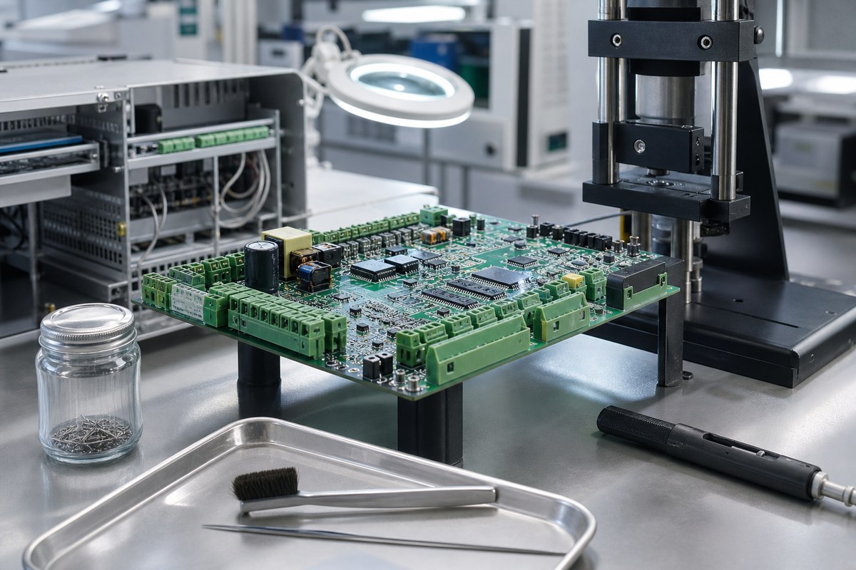
X-ray Supports Selected Hidden and Power-Joint Evidence
We use X-ray for applicable BGA, QFN, exposed-pad and other hidden structures. Coverage, acceptance, sampling and output are defined from the product risk.
An X-ray image cannot prove sensing accuracy, communication or firmware behavior. We combine it with the required electrical evidence.
Programming Remains Connected to Hardware Revision
We control the approved firmware or programming file, target device and identifier. Hardware or firmware changes receive compatibility review for programming, fixtures, calibration and test.
The programming record remains connected to the work order or product identifier where the approved route supports it.
Functional Testing Uses Defined Inputs and Limits
Customer-defined testing may stimulate cell-voltage inputs, current-sense channels, temperature inputs, communications, balancing outputs or control signals. We require the fixture, procedure, firmware, expected values, tolerance and report format.
The result identifies which functions and ranges were tested. It does not automatically prove operation across every battery pack, load, fault, temperature or lifetime condition.
Isolation Evidence Uses the Specified Requirement
We preserve customer-defined creepage, clearance, slots, coating boundaries and high-voltage interfaces during manufacturing. Where an electrical or dielectric test is required, the voltage, duration, leakage limit, fixture, safety control and report are defined.
Your product team establishes the applicable safety requirement. We execute the assigned manufacturing verification and keep its result tied to the build.
Calibration and Golden References Need Control
If the test uses calibration data, golden units or reference fixtures, we identify revision, status and ownership. Changes to a reference can change the meaning of results even when the PCBA is unchanged.
We keep approved test inputs visible and route exceptions through controlled disposition.
Failures, Repairs and Retests Remain Traceable
Failed units are contained and connected to diagnosis, approved repair or rework, verification and final result. Available work-order or serial links support focused retrieval.
This helps your quality team distinguish first-pass performance from final acceptance and investigate recurring defects.
Why BMS Customers Use Our Evidence Route
We separate manufacturing structure, electrical connectivity, firmware and defined function, then provide the evidence assigned to each. Your team receives a more accurate picture than a simple “tested” statement.
This supports controlled BMS PCBA release while preserving pack- and vehicle-level validation responsibilities.
Send Your BMS Test Requirements
Send product files, BOM, CPL, assembly drawing, firmware, programming instructions, cell and sensor simulation requirements, communication protocol, fixture data, isolation test, limits, quantities, serialization and report format to sales@ebestpcba.com.
We will return the proposed inspection and test matrix, missing inputs and evidence available.