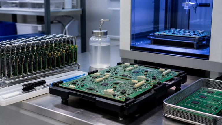
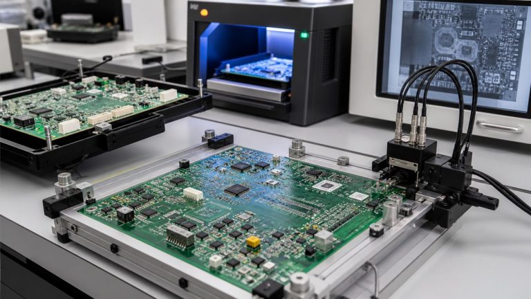
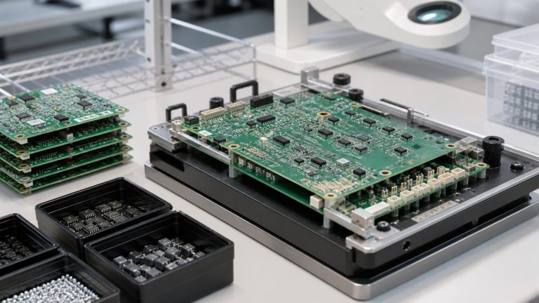
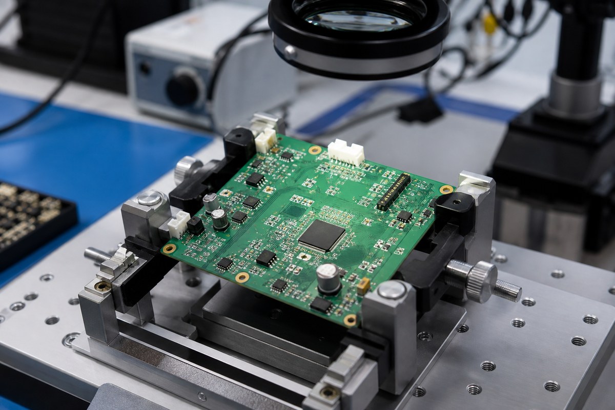
We review medical PCB and PCBA layouts for fabrication, assembly, inspection and test before production release. Our engineers compare the complete manufacturing package with the proposed route and identify file conflicts, process limits, inaccessible joints, material questions and missing acceptance requirements.
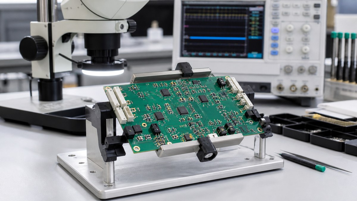
You receive actionable DFM questions and approved dispositions connected to the released revision. We do not replace the medical-device manufacturer’s design, safety or regulatory validation. We ensure the approved physical design can be manufactured and documented as intended.
Medical PCB DFM Checklist
| Review area | What we check | Output |
|---|---|---|
| File control | Agreement among PCB, BOM, CPL, assembly and drawings | Released data list |
| PCB construction | Material, stack-up, copper, drill, finish and tolerances | Approved fabrication basis |
| Isolation and high voltage | Specified creepage, clearance, slots and coating boundaries | Manufacturing-risk questions |
| Assembly | Land patterns, polarity, fine pitch, thermal mass and access | Assembly DFM response |
| Cleanliness and coating | Materials, keep-outs, cleaning, cure and acceptance | Controlled process requirements |
| Inspection and test | Hidden joints, test points, programming and fixtures | Coverage plan |
We Verify That Every File Describes One Revision
We reconcile Gerber or ODB++, drill files, stack-up, fabrication drawing, BOM or AML, CPL, assembly drawing and mechanical data. Part number, revision, board outline, connector location, polarity and critical notes must agree.
Conflicts are returned before CAM or placement programming. Approved answers remain linked to the work order.
PCB Construction Needs Measurable Requirements
We review material grade, finished thickness, layer copper, impedance, hole structure, surface finish, solder mask, dimensions and tolerances. Vague terms such as “medical grade” do not define a buildable PCB.
The approved stack-up and drawing become the fabrication baseline and support repeat orders.
Isolation Features Must Survive Manufacturing Tolerance
Where the customer identifies high-voltage or isolation requirements, we review the physical creepage, clearance, slots, board edges and coating keep-outs for manufacturability. We identify locations where drill, routing, copper or mask tolerance could reduce the specified spacing.
The customer defines voltage, environment and applicable safety standard. We preserve the approved geometry and provide relevant manufacturing evidence.
Land Patterns and Paste Must Fit the Assembly Process
We review pad, solder-mask and paste geometry, component package, orientation, spacing, thermal mass and rework access. Fine-pitch, QFN and BGA packages receive focused inspection planning.
When the design creates a solder or access risk, we return the specific feature and proposed manufacturing response rather than a generic DFM score.
Mechanical and User Interfaces Need Controlled Data
We check board outline, mounting holes, connector fit, component height, enclosure keep-outs, switches, sensors and cable direction. Medical assemblies often combine electrical and physical interfaces that cannot be verified from Gerber data alone.
Mechanical files and assembly sequence allow these risks to be resolved before tooling.
Cleanliness and Coating Affect Layout Decisions
If cleaning, ionic cleanliness or conformal coating is required, we review material compatibility, spacing, masking access, connector contacts, test points and acceptance criteria.
The approved requirement enters the manufacturing and inspection route. Coating is not used to hide an uncontrolled surface condition.
We Plan Inspection and Test Access Before Release
SPI, AOI and X-ray cover different assembly risks. ICT, flying probe, programming and functional tests require suitable access, fixtures, software and limits.
We identify uncovered risks and missing test inputs before fabrication, when the layout can still be corrected deliberately.
What You Receive From Our DFM Review
- file and revision conflicts;
- PCB construction and tolerance questions;
- assembly and mechanical risks;
- cleanliness or coating requirements needing clarification;
- inspection and test coverage proposal;
- approved responses retained with production release.
Send Your Medical PCB for DFM Review
Send product files, stack-up, fabrication drawing, BOM, CPL, assembly and mechanical drawings, voltage and isolation requirements, cleanliness or coating specification, programming files, test procedure and quantities to sales@ebestpcba.com.
We will return the manufacturability questions, proposed route and evidence available for your build.
What Your Team Receives From Our Layout Review
We return comments against the actual drawing, Gerber data, BOM and assembly files you supplied. Each issue identifies the affected feature, the manufacturing reason and the decision we need from you. This keeps layout ownership with your engineering team while giving purchasing and quality teams a clear record of what was resolved before the medical PCBA build.