Digital Manufacturing Control
Software can compare geometry, generate machine data and connect records, but it does not decide which customer requirement is correct. We combine digital checks with engineering review and controlled approval. The useful result is a released manufacturing package and retrievable evidence, not a screenshot from a named tool.
Customer files remain the starting authority
Gerber or ODB++, drill, drawing, stack-up, BOM, centroid and assembly data enter the review as one revision. Firmware, test and mechanical sources are included where applicable.
Software cannot resolve a conflict between two approved-looking files. Our engineer raises the question and records the customer disposition.
CAM preparation turns PCB data into production information
Fabrication data are checked for layers, units, polarity, drill groups, outline, panel and special structures. Manufacturing features and tooling are prepared according to the released route.
Any adjustment that changes customer design intent follows the approval process.
Automated DFM checks find repeatable geometry conditions
Rules can flag spacing, annular ring, mask, drill, edge and other manufacturability conditions. These checks are efficient for large datasets.
An automated flag is not automatically a defect, and an unflagged feature is not automatically safe. Application requirements and process context still need engineering judgment.
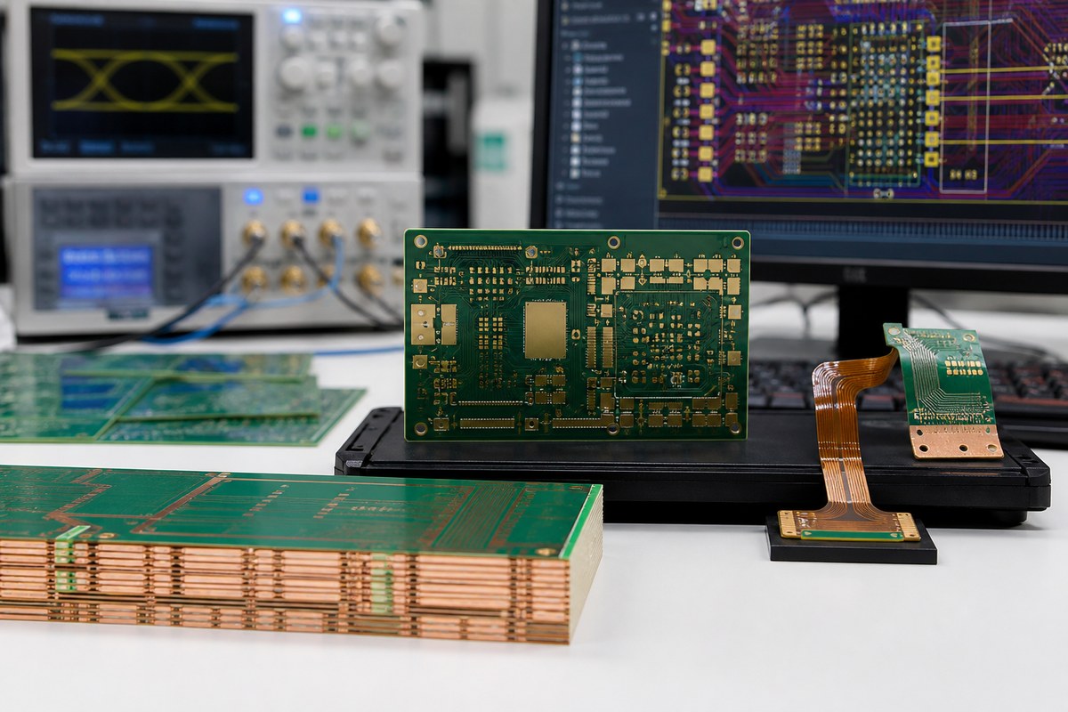
Stack-up and impedance tools support controlled proposals
Approved material, dielectric, copper and target impedance can be used to prepare a manufacturable stack-up and geometry proposal. Calculation inputs and assumptions need alignment with the customer’s design basis.
Coupon measurement provides separate production evidence for defined structures.
BOM tools organize identity and sourcing questions
Part-number normalization and comparison can expose missing manufacturer part numbers, duplicate references, quantity mismatches and package conflicts. Lifecycle or availability data can be reviewed as dated inputs.
Software suggestions do not authorize an alternate component. Customer approval remains the release boundary.
Centroid and assembly data create machine programs
Reference, X/Y position, rotation and side support placement programming. The data are compared with the assembly drawing, BOM and panel orientation.
Rotation conventions and polarity need first-article verification because different source systems can represent them differently.
Inspection programs require product-specific setup
SPI, AOI and X-ray systems use programmed regions and criteria. Product geometry, component appearance and access influence coverage and false calls.
We control the applicable program revision and operator disposition. Automation is not described as complete defect detection.
Test software proves only defined functions
ICT and functional systems need net data, fixtures, firmware, sequences and limits. The program revision is linked to the applicable product configuration.
A pass result is meaningful only with the tested conditions and acceptance rules.
MES and production records connect events
Within an agreed scope, EBest’s MES-related records can connect a released work order with material identification, process steps and available quality results. Lot or serial depth depends on identifiers and station connections.
We define fields, reports and retention rather than promising unlimited data.
Revision control prevents correct software from using wrong data
CAM, placement, inspection, programming and test outputs must all derive from the approved product revision. When customer data change, affected programs are reviewed and re-released.
A technically correct program for an old revision remains the wrong program.
Data conversion needs an independent visual check
Importing CAD, BOM or centroid data can change units, rotation, layer interpretation or character fields. Our engineers compare converted outputs with the drawings and known product features before release.
The original customer source remains preserved. Correcting a conversion does not grant authority to redesign the source data.
Permissions and backups protect controlled information
Product files, firmware and manufacturing programs require appropriate access and version control. Operational security details are not published, but the project can define transfer, approval, retention and deletion requirements for sensitive data.
Backup and recovery support continuity; they do not replace revision approval or customer confidentiality rules.
Exception reports need owners and closure
Software may generate many warnings. EBest assigns relevant findings to engineering, sourcing, production, quality or the customer and records the disposition. Suppressed alerts need a reason when they affect release.
This prevents a long automated report from becoming paperwork that nobody uses to control the build.
Human review remains necessary at decision points
Engineers evaluate tradeoffs, application context, capability and evidence. Quality personnel review exceptions and release status. Customer design authorities approve changes to product intent.
This division keeps automation fast while preserving accountability.
Digital control map
| Digital activity | What it supports | Required human decision |
|---|---|---|
| CAM/DFM analysis | Geometry and process preparation | Disposition of design-impacting findings |
| BOM comparison | Part identity and sourcing gaps | Approval of alternatives |
| Placement/inspection programming | Repeatable machine setup | First article and coverage review |
| Functional-test program | Defined behavior and limits | Customer acceptance of scope |
| MES record link | Traceability and retrieval | Field, granularity and retention agreement |
Data needed for a clean digital handoff
- One identified product and revision package.
- Complete PCB image, drill and drawing data.
- Stack-up, materials and special structures.
- BOM, centroid and assembly drawing.
- Approved alternatives and change rules.
- Firmware and test program sources.
- Critical characteristics and acceptance limits.
- Traceability fields and report requirements.
What EBest returns
Our engineers can return data conflicts, DFM dispositions, controlled manufacturing outputs, program revision links and the available production-record map. We avoid publishing unverified software brand claims; customer confidence should come from the decisions and records the workflow produces.
Discuss Your Project With Our Engineers
Send us your PCB and assembly data, revision rules and required records. We will explain how we convert them into a controlled digital manufacturing package for your project.
Email sales@ebestpcba.com with the current revision and expected quantity.
For your PCB or PCBA project, we will define the controlled source data, approval workflow and records before release. You can see how each digital check supports a manufacturing decision for the current revision.