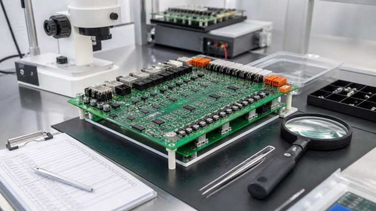
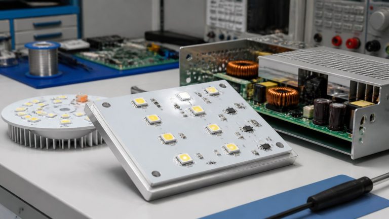
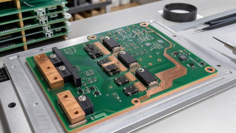
We manufacture power-electronics PCBAs from a controlled construction, authorized component set and repeatable soldering and test route. Before a prototype becomes a regular order, our engineers close temporary copper definitions, hand-soldering adjustments, substitute power parts, thermal-interface changes and incomplete high-voltage or load-test requirements.
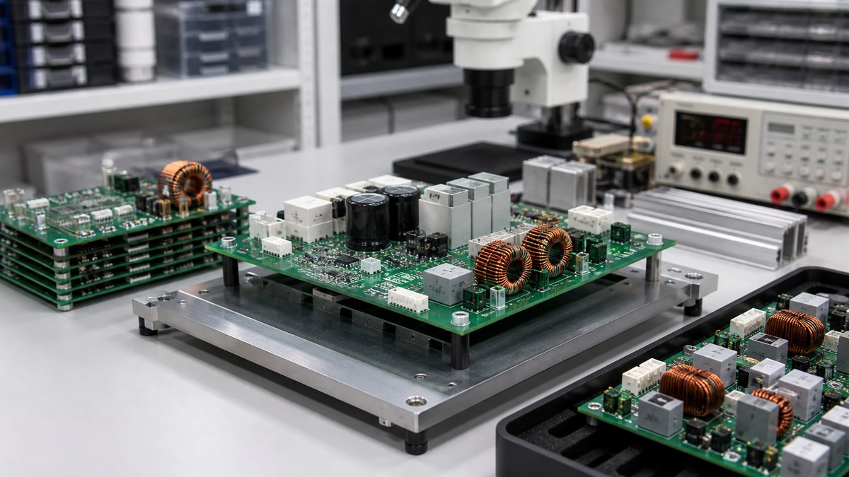
You receive a production-readiness review showing what will be built, how critical power and isolation features will be controlled, and which manufacturing evidence will support release.
Power Production-Release Checklist
| Risk | Our control | Evidence |
|---|---|---|
| Unclear copper construction | Release layer-specific starting and finished copper | Approved stack-up |
| Prototype-only power part | Review MPN, source, lifecycle and alternatives | Released BOM |
| Thermal-path variation | Control vias, exposed pads, heat sinks and interfaces | Process and inspection record |
| High-voltage geometry | Preserve specified creepage, clearance and slots | Manufacturing and dimensional evidence |
| Undefined test | Release fixture, load, firmware, limits and report | Product-linked result |
We Release One Complete Product Definition
Our engineers reconcile PCB data, stack-up, fabrication drawing, BOM, CPL, assembly drawing, mechanical interfaces and test package. Copper, holes, isolation features, polarity and power-terminal information must agree.
Approved files remain connected to the customer part, revision and work order. Changes receive a new decision before repeat production.
Prototype Power Decisions Become Controlled Instructions
Prototype teams may add copper, change thermal pads, hand-solder terminals, substitute MOSFETs or adjust heat-sink hardware. We identify which changes require a design update, approved material, fixture, stencil, soldering route or test condition.
The production team receives documented controls rather than verbal instructions from the prototype engineer.

Our BOM Review Protects Power-Component Identity
We check manufacturer part numbers, ratings, package, source, lifecycle and substitution rules for power semiconductors, magnetics, capacitors, relays, shunts, connectors and control devices.
Alternative parts are reviewed for electrical, thermal, mechanical, soldering, programming and test effects before customer approval.
Copper and Thermal Features Follow the Released Build
We control layer copper, trace and plane geometry, plated current paths, via arrays, exposed pads and thermal interfaces. Heavy copper is reviewed with spacing, resin fill, flatness and assembly thermal mass.
Applicable structural, paste, solder or X-ray evidence is planned for critical features. System operating temperature remains validated under customer conditions.
Isolation Features Stay Visible Through Manufacturing
We review the customer’s specified creepage, clearance, routed slots, board edges, coating keep-outs and high-voltage interfaces against manufacturing tolerances.
The customer defines working voltage, environment and applicable safety standard. We preserve the approved physical requirement and identify any feature that cannot be manufactured as drawn.
The Pilot Uses the Intended Soldering and Test Route
Large copper and high-mass components can require different stencil, reflow, selective or manual soldering controls. We use the intended production route for pilot evidence and first-article verification.
Electrical and functional tests use the defined fixture, firmware, inputs, loads, limits and report. A low-power pass is not represented as full-load or lifetime validation.
Traceability Supports Repeat Builds and Failure Review
MES-related records can connect the released work order, identified material, process stations and available inspection or test information. Project-specific lot or serial links are defined before production.
This helps your team compare repeat orders and investigate a component, process or field concern with known evidence.
Why Power Customers Use Our Production Handoff
We connect electrical power intent to copper, parts, thermal interfaces, isolation, soldering and test. Your team can see which prototype decisions became permanent controls and what evidence supports release.
This reduces late process changes and inconsistent repeat builds.
Send Your Power PCBA for Readiness Review
Send product files, stack-up, copper definitions, BOM, CPL, assembly drawing, current and voltage conditions, thermal data, isolation requirements, prototype issues, test procedure, quantities and evidence needs to sales@ebestpcba.com.
We will return the open production decisions, proposed controls and evidence plan.
What We Ask You to Freeze for Repeat Orders
Before repeat production, we ask you to approve the PCB revision, BOM and alternates, firmware, thermal-interface materials, mechanical hardware, test limits and required records. We then release one controlled package for purchasing and manufacturing. This prevents temporary prototype decisions from becoming undocumented production changes and gives your team a stable basis for later orders.