EBest PCBA Manufacturing
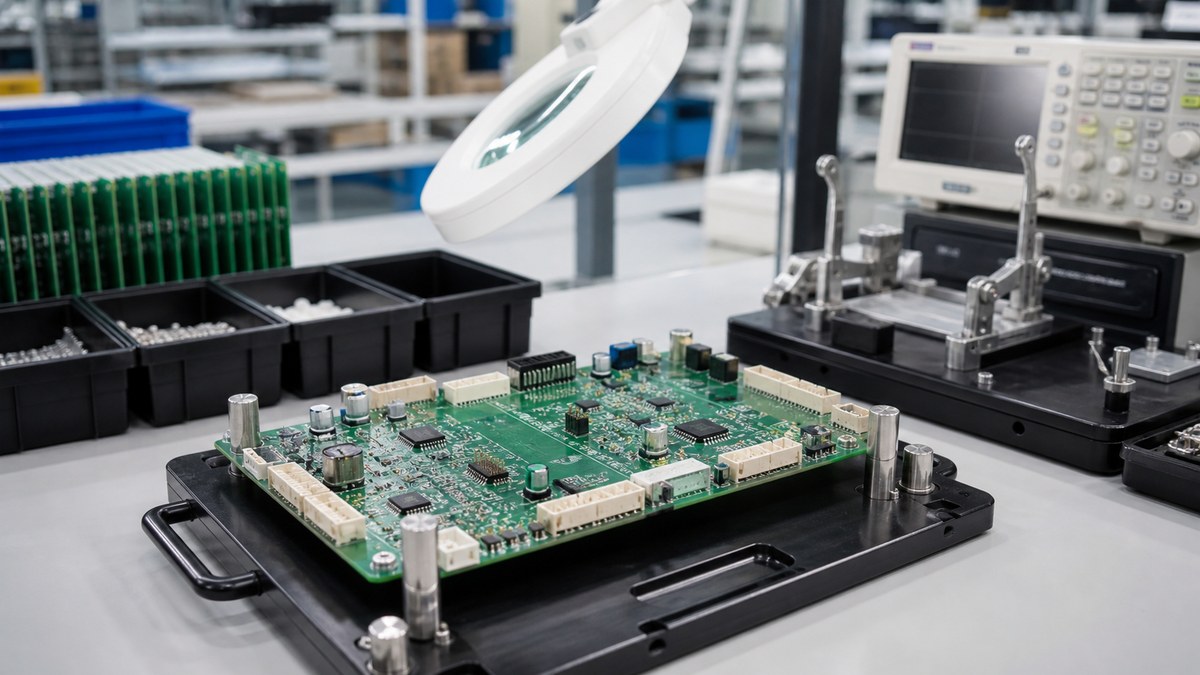
PCB assembly is not simply placing parts on a board. The delivered PCBA depends on released data, authorized components, tooling, solder processes, inspection, programming, test and traceability. We connect those stages so the customer can understand both the workflow and the evidence available for the actual build.
Assembly begins with engineering release
We reconcile the bare PCB revision, assembly drawing, BOM, centroid file, do-not-fit data, firmware and test requirements. Conflicts are returned before kitting or programming.
The approved package becomes the work-order baseline.
The bare PCB must match the assembly need
Surface finish, mask, pad geometry, panel, flatness and special via structures influence soldering. Our assembly review identifies PCB conditions that need coordination with fabrication.
A PCB electrical pass does not mean it is automatically optimized for assembly.
BOM control authorizes the physical product
Complete manufacturer part numbers, approved alternatives and source restrictions guide purchasing. We check package and reference alignment with assembly data.
Supply pressure does not authorize an unapproved replacement.
Incoming material is prepared for the process
Available identity, quantity, packaging and special handling are reviewed. Moisture-sensitive, programmed, customer-supplied or otherwise controlled parts follow applicable instructions.
Shortages and ambiguous parts are resolved before release where possible.
Panel, stencil and fixtures create repeatable tooling
Panel support, fiducials, tooling holes, stencil apertures and pallets depend on board geometry, package mix and solder route. Tooling revision is linked to the product.
Prototype adjustments are recorded before repeat production.
Solder paste printing sets an early process condition
Paste material, storage, preparation, stencil, support and printing setup influence deposits. SPI may be used to monitor selected conditions before placement.
Paste inspection does not prove final joint quality, so later controls remain necessary.
Placement uses controlled part and position data
Machine programs use reference, position, rotation and side. Feeder setup and component identity must match the released BOM. First-article verification catches convention or polarity errors before the run continues.
Manual placement, where required, follows the same configuration boundary.
Reflow is matched to board and component thermal behavior
The product’s copper, thickness, component mass and materials affect heating. Our process engineers establish the applicable route within approved component and PCB limits.
If a profile record is required, the representative board and report are agreed.
Through-hole and mixed assembly need their own route
Connectors, transformers, terminals and other through-hole parts may use selective, wave or controlled hand soldering depending on design and volume. Hole, pad, copper and access affect fill and heating.
Customer criteria and any mechanical hardware instructions are included in the work instruction.
Cleaning and coating are project-specific
Flux, sensitive components, cleanliness requirements and coating plans determine whether and how the assembly is cleaned. Coating adds material, masking, cure and inspection requirements.
A wash or coating step is not represented as an environmental qualification without defined tests.
Inspection methods cover different assembly risks
First article, SPI, AOI and X-ray may be selected according to setup, visible features and hidden joints. Through-hole fill and hardware need applicable inspection.
The coverage map states what each method can detect and its limits.
Programming and test verify the defined configuration
Approved firmware, checksum or revision and procedure are controlled. ICT, flying probe or functional testing needs accessible data, fixtures, sequence and limits.
A functional pass applies only to the stated conditions.
Failures and rework remain controlled
Failed units are identified, segregated and reviewed. Authorized repair and retest are retained within the agreed history.
Customer restrictions and deviation approvals are linked to the affected product.
Repeat production uses the approved assembly baseline
Before a repeat order, we recheck BOM availability, customer revision, tooling, machine programs, firmware, test software and open deviations. Changes are reviewed for new first-article, inspection or functional evidence.
A successful earlier lot provides history but does not authorize expired material or an old program.
Assembly workflow and evidence
| Stage | Main control | Evidence by agreement |
|---|---|---|
| Release | One approved data package | Work-order and revision link |
| Material | Authorized BOM and identity | Available lot/date-code records |
| SMT/THT | Tooling, setup and instructions | Traveler or station status |
| Inspection | Risk-matched SPI/AOI/X-ray | Selected quality results |
| Programming/test | Approved files and limits | Lot or unit result where configured |
Traceability and shipment release
Within an agreed scope, work-order, lot or serial identifiers can connect to released revisions, available material, process, inspection and test records. Final quantity, packaging, labels and required reports are checked before shipment.
Retention and report delivery are confirmed during quotation.
Files to send for PCBA quotation
- PCB data and fabrication requirements.
- Assembly drawing, BOM and centroid file.
- Approved alternatives and sourcing rules.
- Programming files and instructions.
- Inspection, functional test and limits.
- Cleaning, coating and packaging requirements.
- Traceability, reporting and retention.
- Prototype and repeat-volume expectations.
What EBest returns
EBest can return engineering questions, sourcing gaps, proposed assembly route, inspection/test coverage and available production evidence. Send the complete package to sales@ebestpcba.com so our teams can plan one controlled build rather than assemble from disconnected files.
For your assembly, we will confirm sourcing scope, soldering route, programming, inspection, test and shipment records before production. You can approve those controls against the exact PCBA revision and order requirement.