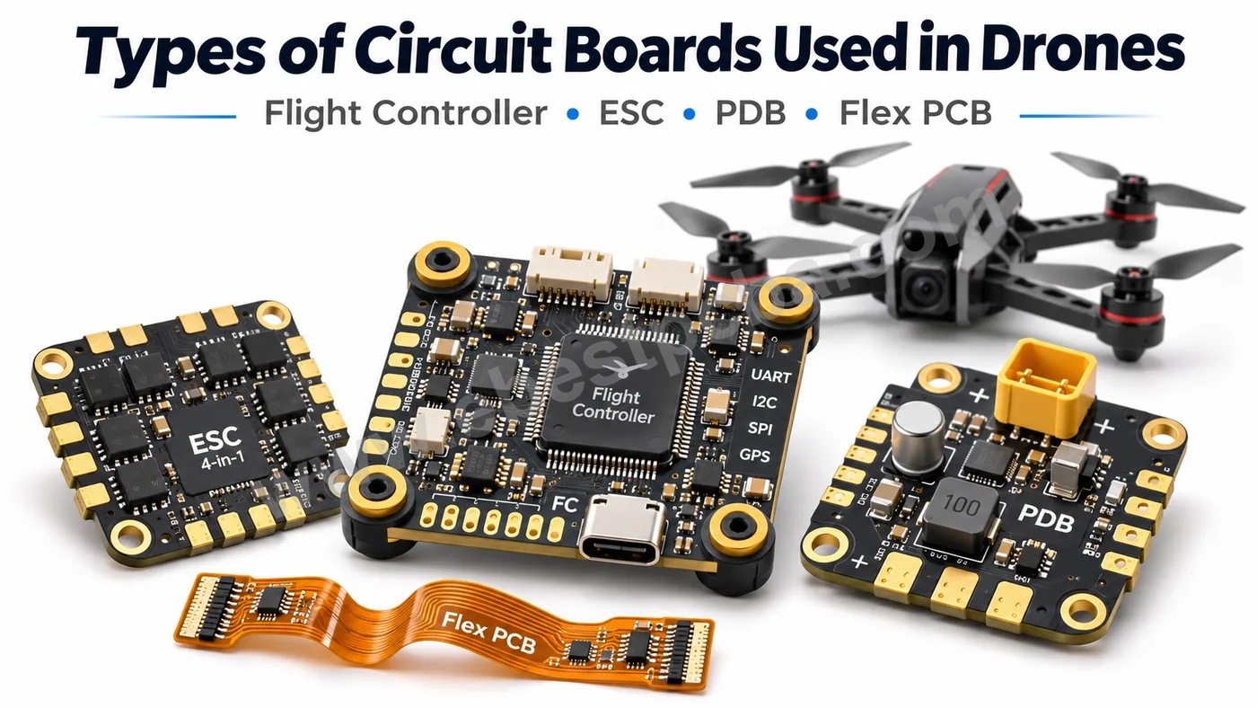
The main types of circuit boards used in drones include flight controller PCBs, electronic speed controller (ESC) boards, power distribution boards (PDBs), sensor boards, communication PCBs, and camera or gimbal control boards. Each performs a specific task, from stabilizing flight and controlling motors to managing power and transmitting data.
These systems use different PCB constructions. Multilayer FR4 is common in flight controllers, heavy copper supports high-current power circuits, and flexible or rigid-flex PCBs fit camera and sensor connections into compact spaces. Choosing the right construction affects weight, electrical performance, thermal management, and reliability.
EBest PCBA provides custom drone PCB manufacturing and assembly services, covering PCB fabrication, component sourcing, SMT assembly, testing, and DFM review. With 4 SMT production lines, No MOQ, and dedicated engineering support, we help UAV manufacturers turn PCB designs into assembled boards for prototypes and repeat production.
What Are the Main Types of Circuit Boards Used in Drones?
Drone circuit boards are classified by their electronic functions, including flight control, motor drive, power distribution, sensing, communication, and imaging. A compact drone may combine several functions on 1 board, while a larger UAV often uses separate electronic modules.
| Circuit Board | Main Function | Typical Components |
|---|---|---|
| Flight Controller PCB | Flight stabilization | MCU, IMU, barometer |
| ESC PCB | Motor speed control | MOSFETs, gate drivers |
| Power Distribution Board | Battery power delivery | Copper planes, connectors |
| Sensor PCB | Motion and position sensing | Gyroscope, accelerometer |
| Communication PCB | Wireless data transmission | RF ICs, filters |
| Navigation PCB | Position and heading data | GNSS receiver, compass |
| Camera PCB | Image capture and processing | Image sensor, processor |
| Gimbal Control PCB | Camera stabilization | Motor drivers, sensors |
| Battery Management PCB | Battery monitoring and protection | Monitoring ICs, protection circuits |
Flight Controller PCB
The flight controller processes sensor data and calculates the control outputs needed to keep the drone stable. Its main circuits include:
- MCU: Runs flight-control algorithms.
- IMU: Measures acceleration and angular velocity.
- Barometer: Supports altitude estimation.
- Communication interfaces: Connect sensors, receivers, and ESCs.
ESC PCB
An ESC controls brushless motors by switching current through power MOSFETs. Its PCB must handle high-current switching, voltage transients, and heat generated during operation.
Power Distribution Board
A PDB routes battery power to ESCs and onboard electronics. Depending on the design, it may also integrate voltage regulators, current sensors, or protection circuits.
Sensor and Navigation PCBs
These boards collect information such as acceleration, angular velocity, air pressure, and GNSS position. Some sensors are mounted directly on the flight controller, while others use separate boards.
Communication and Imaging PCBs
RF boards support telemetry, receiver links, and video transmission. Camera and gimbal boards manage image sensors, stabilization motors, and related interfaces.
How Do Drone Circuit Boards Work Together?
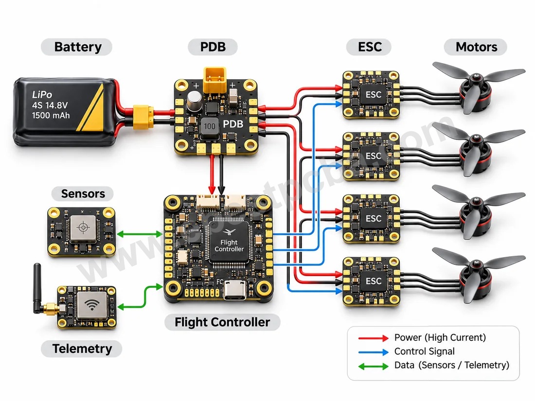
Drone circuit boards operate as a connected control and power system. The battery supplies energy, sensors provide flight data, the flight controller calculates corrections, and ESCs translate those commands into motor output.
A typical drone control sequence follows 6 steps:
- Power supply: The battery delivers power through distribution and regulation circuits.
- Sensor feedback: The IMU and other sensors measure aircraft movement.
- Command reception: The receiver supplies pilot or system commands.
- Flight calculations: The flight controller determines the required response.
- Motor control: ESCs adjust the electrical drive to individual motors.
- Continuous correction: New sensor measurements allow the controller to update its output.
Camera, navigation, and telemetry modules exchange additional data with the flight controller or other onboard processors. High-current motor circuits and low-voltage control signals require different grounding, filtering, and routing arrangements.
What Is the Difference Between a Flight Controller PCB, ESC, and PDB?
The flight controller manages aircraft behavior, the ESC drives the motors, and the power distribution board delivers electrical power. Their different functions create distinct PCB design and manufacturing requirements.
| Feature | Flight Controller | ESC | PDB |
|---|---|---|---|
| Main Task | Flight calculations | Motor drive | Power distribution |
| Current | Relatively low | High | High |
| Main Concern | Signal noise | Heat and switching | Voltage drop |
| PCB Priority | Grounding and routing | Thermal design | Copper capacity |
| Typical Components | MCU, IMU | MOSFETs, drivers | Connectors, copper planes |
Flight Controller PCB Design Priorities
- Stable power rails for sensitive ICs.
- Suitable ground reference planes.
- Proper IMU placement and mechanical support.
- Reliable connections to sensors and ESCs.
ESC PCB Design Priorities
- Low-impedance high-current paths.
- Thermal management around MOSFETs.
- Suitable copper thickness and via connections.
- Controlled switching-current return paths.
Power Distribution PCB Design Priorities
- Sufficient conductor current capacity.
- Secure battery and motor-power connections.
- Appropriate electrical clearances.
- Low voltage drop under peak load.
How EBest PCBA Supports These Requirements
EBest PCBA engineers review manufacturing details for each board type:
- Flight controllers: Fine-pitch component layouts, solder-pad design, and assembly clearance.
- ESC boards: Copper thickness, power-component footprints, and thermal requirements.
- Power distribution boards: High-current conductors, connector mounting, and soldering processes.
Our integrated PCB fabrication and SMT assembly services help customers identify manufacturing concerns before production.
Which Types of PCBs Are Used in Drone Electronics?
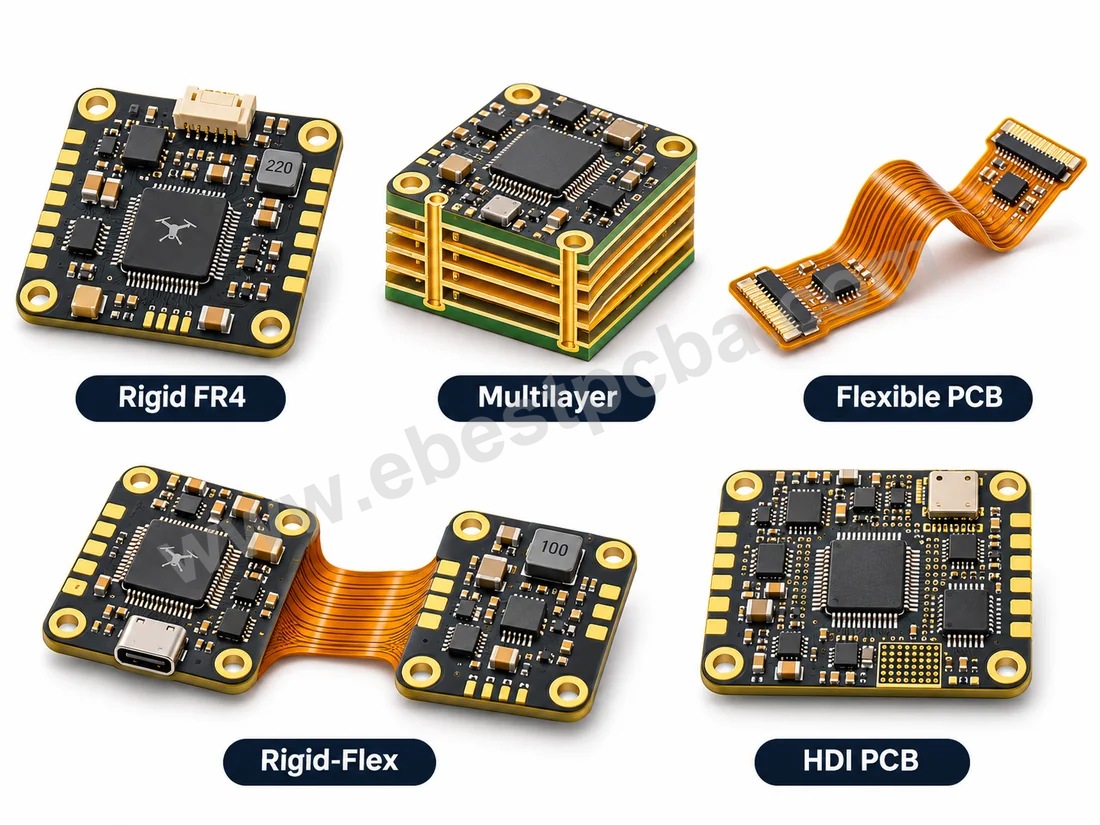
Drone electronics mainly use rigid, multilayer, flexible, rigid-flex, HDI, and heavy copper PCBs. Each construction addresses different space, electrical, and mechanical requirements.
| PCB Type | Main Advantage | Drone Application |
|---|---|---|
| Rigid FR4 | Mechanical stability | Flight controller |
| Multilayer PCB | Dense signal routing | Control and navigation |
| Flexible PCB | Lightweight connections | Camera and gimbal |
| Rigid-Flex PCB | Integrated 3D packaging | Compact sensor modules |
| HDI PCB | Fine-pitch interconnection | Miniature controllers |
| Heavy Copper PCB | Higher current capacity | ESC and PDB |
| RF PCB | High-frequency performance | Communication modules |
Rigid and Multilayer PCBs
FR4 supports SMT assembly and offers a practical balance of mechanical strength and cost. Multilayer construction adds routing space and dedicated power or ground planes.
Flexible PCBs
Flexible PCBs are useful when circuits must bend around mechanical structures or connect moving assemblies. Common applications include:
- Camera signal cables.
- Gimbal interconnects.
- Folded sensor assemblies.
- Space-constrained internal connections.
Rigid-Flex PCBs
Rigid-flex PCBs combine rigid component areas with integrated flexible sections. They can reduce separate cables and connectors in compact modules.
HDI PCBs
HDI uses microvias and fine routing to connect densely packaged components in miniature control and processing assemblies.
Heavy Copper PCBs
Heavy copper construction supports higher current loads in power electronics. Its suitability depends on current, conductor geometry, and thermal requirements.
EBest PCBA Manufacturing Support
EBest PCBA supports FR4 multilayer, HDI, flexible, rigid-flex, and heavy copper PCB projects with component sourcing and PCBA assembly. DFM review covers:
- Stackup and copper weight: Suitability for fabrication.
- HDI features: Microvia structures and fine routing.
- Flexible sections: Bend areas, stiffeners, and transitions.
- Assembly compatibility: Component spacing, soldering, and inspection access.
How Do You Choose PCB Materials and Layer Counts for Drones?
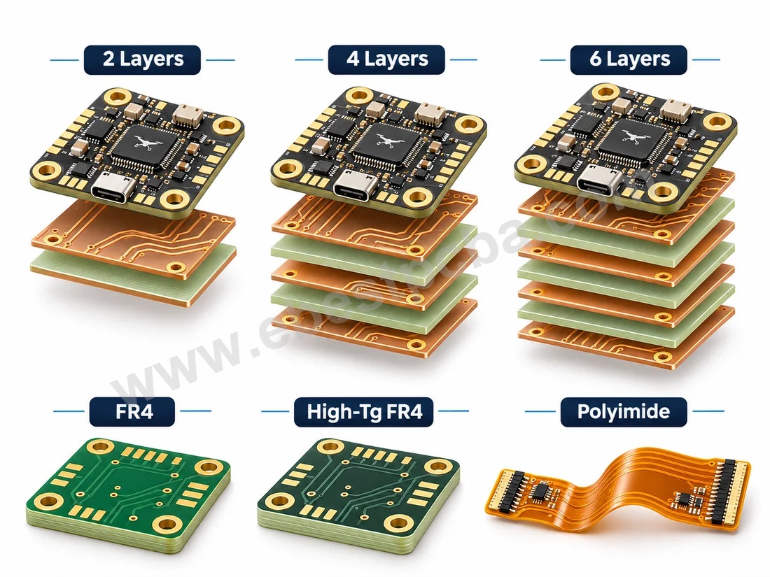
Choose PCB material and layer count according to current, signal density, temperature, vibration, and space constraints. Multilayer FR4 meets many flight-control needs, while specialized materials support flex, RF, and thermal designs.
PCB Material Selection
| Material | Main Property | Suitable Application |
|---|---|---|
| FR4 | Balanced performance | Controllers and sensors |
| High-Tg FR4 | Higher glass-transition temperature | Thermally demanding assemblies |
| Polyimide | Flexibility | Camera and gimbal FPC |
| Low-Loss RF Laminate | Lower signal loss | RF communication |
| Metal-Core Substrate | Heat spreading | Selected power modules |
PCB Layer Count
| Layer Count | Typical Use | Main Consideration |
|---|---|---|
| 2 Layers | Simple interfaces | Limited routing space |
| 4 Layers | Flight controllers | Ground and power planes |
| 6 Layers | Dense control circuits | Greater routing flexibility |
| 8+ Layers | Complex electronics | High-density integration |
These are application examples, not fixed UAV specifications. A 4-layer flight controller may use dedicated reference planes; denser systems can require additional layers.
Key Selection Factors
- Copper weight: Current and temperature rise.
- Dielectric thickness: Impedance and insulation.
- Material properties: Thermal and electrical requirements.
- Mechanical limits: Weight, mounting, and vibration.
- Assembly requirements: Component packages and soldering.
What Are the Main Drone PCB Design Challenges and Solutions?
Key drone PCB design challenges include electrical noise, current capacity, heat, vibration, and limited assembly space. Address these early in layout rather than after fabrication.
1. High-Current Routing
- Calculate conductor width and copper thickness.
- Check voltage drop at peak load.
- Review high-current vias and connectors.
2. Thermal Management
- Provide copper heat-spreading areas.
- Add thermal vias where appropriate.
- Evaluate airflow and enclosure temperature.
3. Electrical Noise
- Maintain continuous reference planes.
- Keep switching loops compact.
- Place decoupling near IC power pins.
- Separate sensitive analog traces from switching nodes.
4. Mechanical Vibration
- Secure heavy components.
- Specify connector retention.
- Review stress near mounting holes.
- Validate mechanical performance under expected conditions.
5. High-Density Assembly
- Check fine-pitch land patterns.
- Reserve test and inspection access.
- Review stencil apertures.
- Plan panelization before fabrication.
6. RF Signal Integrity
- Define impedance targets.
- Maintain reference planes.
- Minimize routing discontinuities.
- Choose suitable laminates.
Which PCBs Are Best for FPV, Camera, and Industrial Drones?
FPV drones favor compact integration, camera drones require reliable imaging connections, and industrial UAVs may need high-current power electronics or additional sensor interfaces.
| Drone Type | Common PCB Selection | Priority |
|---|---|---|
| FPV Drone | AIO FC/ESC, multilayer | Low weight |
| Camera Drone | Multilayer, FPC | Imaging connections |
| Mapping UAV | Sensor, RF, multilayer | Signal integrity |
| Agricultural UAV | Heavy copper, power PCB | Current capacity |
| Inspection UAV | Camera, RF, rigid-flex | Compact integration |
| Cargo UAV | High-current power PCB | Thermal performance |
FPV Drones: A compact flight-controller and ESC stack or AIO board reduces wiring and packaging space.
Camera Drones: Flexible circuits connect imaging modules and gimbals in moving or space-constrained areas.
Industrial and Agricultural UAVs: Power distribution, communication, sensors, and payload interfaces determine the construction and protection needs.
What Are the Manufacturing and Assembly Requirements for Drone PCBs?
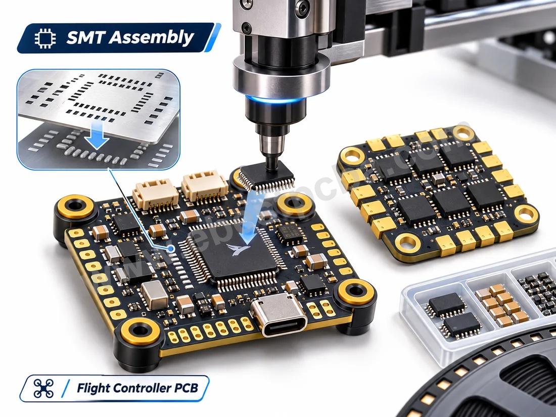
Drone PCB manufacturing needs accurate placement, reliable soldering, appropriate thermal processes, and inspection methods matched to the assembly. Flight controllers, sensor boards, and ESCs each require different process controls.
Our drone PCB assembly service coordinates PCB fabrication, component sourcing, SMT assembly, and inspection for custom UAV electronics.
EBest PCBA Manufacturing Capabilities
| Capability | EBest PCBA Specifications | UAV Applications |
|---|---|---|
| PCB Types | FR4, HDI, FPC, Rigid-Flex | Flight Control, Sensors, Gimbal |
| PCB Layers | 2–50 Layers, by Construction | Multilayer UAV Electronics |
| Heavy Copper PCB | Project-Specific Copper Weight | ESC, Power Distribution |
| SMT Production Lines | 4 Lines (2 JUKI + 2 YAMAHA) | Drone PCBA Production |
| Minimum Component Size | 01005 | Miniature Flight Controllers |
| BGA Assembly | Down to 0.2 mm Pitch | High-Density Processing Boards |
| SMT Reflow | Nitrogen Reflow Available | Fine-Pitch Soldering |
| Through-Hole Assembly | Wave / Selective Soldering | Power Connectors |
| Solder Paste Inspection | 3D SPI | Solder Deposit Control |
| Optical Inspection | AOI | Component and Solder Inspection |
| X-ray Inspection | X-ray / AXI | BGA and Hidden Solder Joints |
| Electrical Testing | ICT, FCT | Control and Power PCBAs |
| PCB Traceability | MES Single-Board Tracking | Production Records |
| Order Quantity | No MOQ | Prototypes and Pilot Runs |
| PCBA Turnaround | As Fast as 1.5 Weeks* | Prototype and Small-Batch Builds |
Lead times depend on board structure, component availability, assembly complexity, quantity, and test requirements. Maximum layer counts vary by PCB construction.
Flight Controller PCB Assembly
- Stencil design: Control solder-paste volume.
- SMT placement: Position fine-pitch and miniature components.
- Reflow profiling: Match the profile to components and PCB construction.
- Inspection: Verify component placement and solder-joint quality.
ESC and Power PCB Assembly
- Review MOSFET footprints and solder pads.
- Check copper thickness and thermal mass.
- Evaluate power connectors and current-carrying joints.
- Plan soldering access and inspection.
Flexible and Rigid-Flex Assembly
Flex assemblies require suitable board support, stiffeners, fixtures, bend-zone design, and handling throughout production.
How Are Drone PCBs Tested for Reliability?
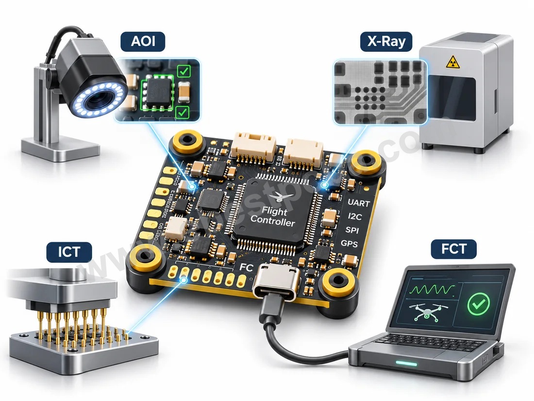
Drone PCB testing combines process inspection with electrical and functional verification. Each technique checks a different defect class and must match the assembly’s requirements.
| Test Method | Main Purpose |
|---|---|
| SPI | Solder-paste inspection |
| AOI | Placement and visible solder defects |
| X-ray | Hidden solder-joint inspection |
| ICT | Electrical connection verification |
| FCT | Circuit-function verification |
| Thermal Testing | Temperature performance |
| Vibration Testing | Mechanical durability |
SPI, AOI, and X-ray
SPI verifies solder-paste deposits, AOI checks applicable visible defects, and X-ray examines hidden joints under BGA or other bottom-terminated packages.
In-Circuit Testing
ICT verifies defined electrical connections and parameters using the required test access and fixtures.
Functional Testing
Customer-defined FCT may check:
- Flight-controller power consumption.
- Sensor and communication interfaces.
- Firmware identification and programming.
- ESC control response and current sensing.
Environmental Reliability
Thermal and vibration tests require agreed limits, duration, equipment, and acceptance criteria. Board-level inspections do not replace product qualification or flight validation. EBest PCBA supports project-defined electrical and functional tests; specialized environmental validation is scoped separately.
What Affects Custom Drone PCB Manufacturing Cost and Lead Time?
Cost and lead time depend on PCB structure, materials, component availability, quantity, assembly complexity, and testing. A complete quotation should cover both bare boards and assembled PCBAs.
Main Cost Factors
| Factor | Pricing Impact |
|---|---|
| PCB Layers | Stackup complexity |
| PCB Material | FR4, flex, RF laminates |
| Copper Weight | Processing requirements |
| HDI Features | Microvias and fine routing |
| Components | BOM pricing and availability |
| Assembly | Package density and processes |
| Testing | Fixtures and test programs |
EBest PCBA supports engineering samples and small production batches with No MOQ, backed by 4 SMT lines for repeat orders.
DFM Review
Our engineering team reviews:
- PCB stackup: Layers, copper, drilling, and materials.
- Component layout: Fine-pitch spacing and assembly access.
- Thermal design: Power-component pads and copper areas.
- Flexible sections: Bend zones, stiffeners, and support.
- Testability: Test points, connectors, and fixtures.
- BOM: Component availability and approved alternatives.
A project team of 1 dedicated sales representative + 3 engineers coordinates manufacturing questions and feedback.
Documents Required for Quotation
- Gerber or ODB++ files.
- BOM with manufacturer part numbers.
- Pick-and-place data and assembly drawings.
- Stackup and material requirements.
- Order quantity and delivery target.
- Programming and testing instructions.
For ESCs or PDBs, also specify voltage, current, connectors, and thermal limits. For RF and flexible boards, specify impedance and bend requirements.
Why Choose EBest PCBA for Drone PCB Manufacturing?
EBest PCBA provides UAV OEMs with PCB fabrication, component sourcing, SMT assembly, inspection, and testing through 1 coordinated project, from early prototypes to repeat production.
What We Offer Drone OEMs
- 20 Years of Manufacturing Experience: PCB and PCBA experience since 2006.
- 1 Sales + 3 Engineers: Coordinated technical review and communication.
- 4 SMT Lines: 2 JUKI and 2 YAMAHA lines.
- 01005 and Fine-Pitch Assembly: For dense control and sensor PCBAs.
- No MOQ: Prototype and small-batch flexibility.
- MES Traceability: Board-level records and production tracking.
- Inspection and Testing: SPI, AOI, X-ray, ICT, and defined FCT.
- PCB + PCBA Services: Fabrication, sourcing, assembly, and testing.
- Quality-System Support: Applicable ISO 9001, ISO 13485, IATF 16949, and AS9100D documentation, subject to the entity and certified scope.
Whether your project uses a multilayer flight controller, high-current ESC, compact sensor PCB, or flexible camera connection, our engineers can review its build requirements before quotation.
Need custom drone PCB manufacturing or assembly? EBest PCBA combines engineering support, 4 SMT lines, MES traceability, and No MOQ. Send Gerber files, BOM, quantity, and delivery target to sales@ebestpcba.com for a DFM review, quotation, and schedule confirmation.
FAQs About Types of Circuit Boards Used in Drones
1. What is the main circuit board in a drone?
The flight controller PCB is the main control board in most drones. It processes sensor measurements and flight commands, then generates motor-control outputs. It commonly integrates an MCU, IMU, power regulation, and communication interfaces.
2. How many circuit boards does a drone have?
A drone may use 1 integrated assembly or several separate boards. Small FPV drones often combine functions on an AIO board, while larger UAVs may have separate control, ESC, power, navigation, communication, and payload PCBs.
3. Can a flight controller and ESC be on the same PCB?
Yes. An all-in-one PCB can integrate flight control and ESC circuits, reducing wiring and assembly space. The layout must manage heat, electrical noise, and sensitive signals near high-current switching circuits.
4. Do drones use flexible or rigid-flex PCBs?
Yes. Flexible PCBs commonly connect cameras and gimbals. Rigid-flex PCBs combine component-mounting sections with integrated flexible connections in compact modules.
5. How many PCB layers are needed for a drone?
Drone PCBs may use 2, 4, 6, or more layers. Simple interfaces can use 2 layers, while compact flight controllers commonly benefit from 4 or more. The requirement depends on routing density, power, and signal integrity.
6. What is an AIO board in an FPV drone?
An AIO board integrates multiple functions, usually the flight controller and ESC, on 1 PCB. It reduces wiring and can save space and weight in compact FPV aircraft.