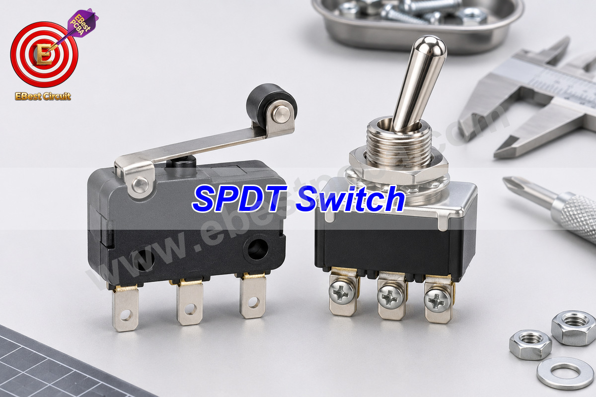
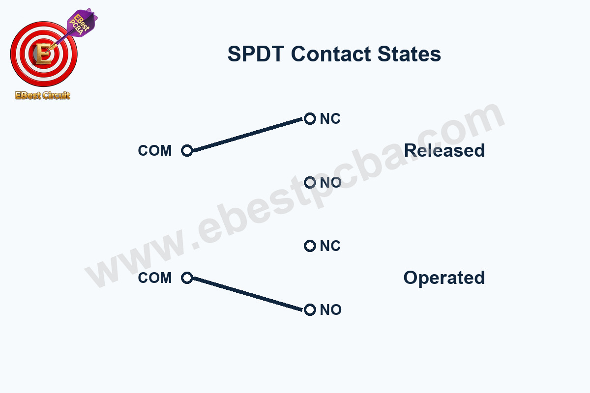
An SPDT switch connects one common terminal to either of two other contacts. Think of a selector with one incoming wire and two possible paths. On a spring-return microswitch, the three contacts are usually marked COM, NC and NO. The diagram and meter test below show which pair conducts before and after you press the lever.
Key Takeaways
- COM connects to NC with a spring-return switch released and to NO when operated.
- Isolate the switch before testing continuity. Locate COM by following which terminal changes partners.
- Check the rating for your load, including the minimum current for a digital input.
What Does the SPDT Switch Symbol Show?
In the SPDT switch symbol, the moving arm starts at COM and points to one of two contacts. NC means the common contact is closed to that terminal with the actuator released. NO means it closes to that terminal when you operate the switch. Read the drawing for your exact part to find the matching pins.
| Switch state | COM to NC | COM to NO |
|---|---|---|
| Free position | Closed | Open |
| Actuated position | Open | Closed |
The SPDT switch diagram shows the two steady states. During transfer, some switches briefly open both paths. Others briefly connect both. Check the transfer specification if the circuit cannot tolerate an interruption or overlap.
How Do ON–ON, ON–OFF–ON and Momentary Actions Differ?
An ON–ON toggle stays in either selected position. An ON–OFF–ON toggle has a middle position that opens both paths. A spring-return switch goes back when you let go. If the catalog uses parentheses to mark a momentary position, check the legend for the part you are ordering.
| Action | Behavior | Example use |
|---|---|---|
| Maintained ON–ON | Stays in either throw position | Select operating mode |
| Maintained ON–OFF–ON | Center position opens both throws | Select either branch or neither |
| Momentary changeover | Returns to its normal state on release | Limit or position detection |
A handheld meter can confirm which contact is closed at each stop. If you need to know what happens during the move, use the datasheet’s transfer specification or capture the contacts with a low-voltage test circuit and a scope.
How Do You Verify SPDT Switch Wiring With a Meter?
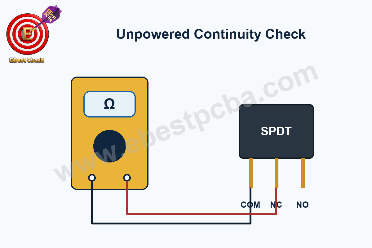
For an SPDT switch wiring check, remove power and disconnect the switch from the circuit so other components cannot provide a false continuity path. Put one probe on COM. With the switch released, the other probe should find continuity at NC. Operate the switch and move that probe to NO. On an unlabeled part, identify the terminal that connects to one partner in one position and a different partner in the other.
- Label the orientation in which you measured the terminals.
- Compare the meter result with the datasheet drawing, paying attention to the viewing side.
- If the part has an LED, identify its separate terminals before connecting a supply.
- Verify function on the final assembly; a footprint can be mirrored even when the schematic is right.
How Can One SPDT Switch Select Between Two Loads?
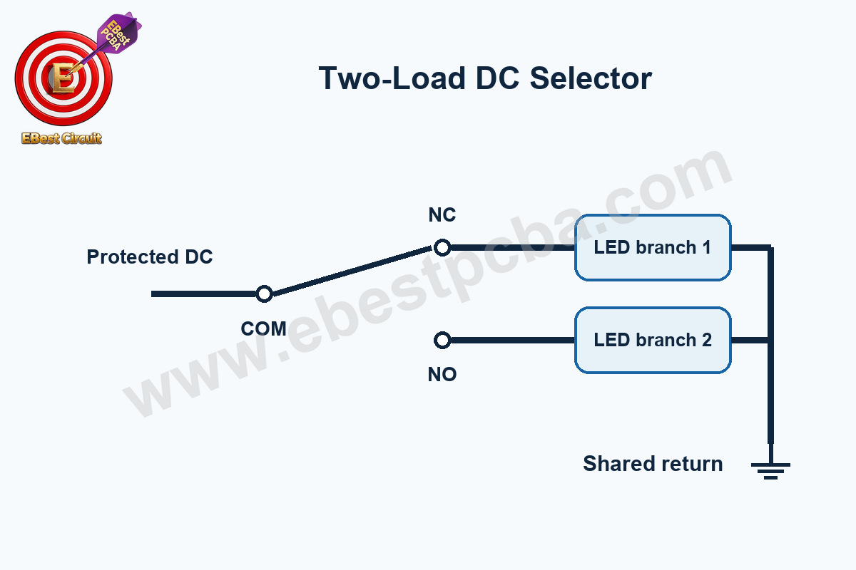
To select one of two LEDs on a 5 V board, bring the supply to COM. Connect each throw to its own LED and series resistor. Both branches return to ground. In either stable position one branch lights. If the switch feeds a digital input, add a pull resistor so the input has a defined level even when both contacts are open.
A motor or valve coil draws current differently from an LED. Check the switch rating for the load type, including startup current and what happens when the contact opens. Choose suppression for the load and verify that it releases at the required speed.
How Do You Size the Load and Read the Contact Rating?
Start with the voltage and load type on the datasheet. A motor draws extra current on startup, a capacitor can draw a sharp pulse at connection, and a coil can arc at the contact when it opens. Compare those conditions with the switch ratings and electrical life.
For the two LED branches above, a 2.0 V forward drop leaves about 3.0 V across a 330 Ω resistor. That gives about 9.1 mA. With a 4.75–5.25 V supply, 1.8–2.2 V forward drop and a ±5% resistor, the estimate spans 7.4–11.0 mA. Use the LED datasheet to check the forward drop at your operating current and temperature.
» I ≈ (VSUPPLY − VF) / R
A digital input can draw very little current. A 10 kΩ pull-up on 3.3 V puts about 0.33 mA through the closed contact before leakage. Compare that with the switch’s minimum applicable load and choose a contact specified for signal use if needed.
How Do SPST, SPDT and DPDT Switches Compare?
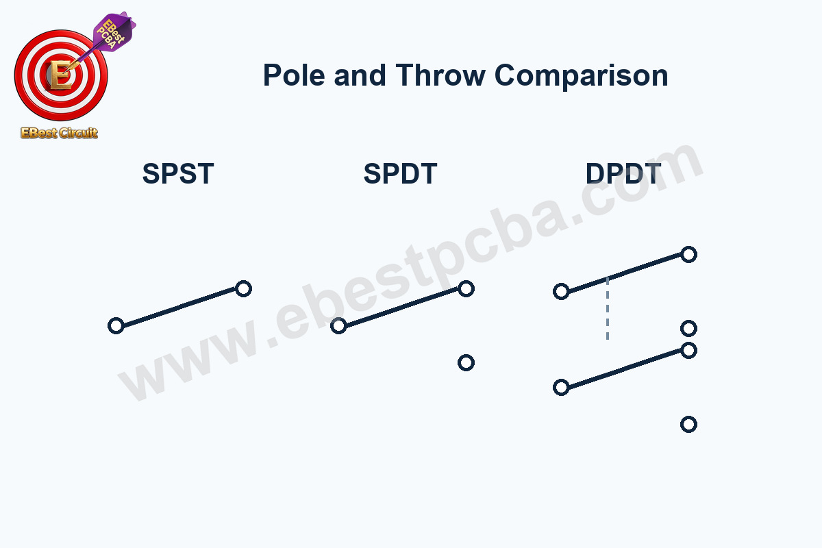
In an SPST vs SPDT switch comparison, count what the moving contact can do. SPST opens or closes one path. SPDT selects between two paths. DPDT switches two independent paths together. Extra pins for an LED or mechanical mounting do not count as throws.
| Contact form | Poles × throws | Common use |
|---|---|---|
| SPST | 1 × 1 | Simple on/off |
| SPDT | 1 × 2 | Source or load selection |
| DPDT | 2 × 2 | Switch two paths together |
What Should You Check Before Ordering an SPDT Switch?
Confirm the contact action and the rating before comparing housings. On a PCB switch, also check the pin pitch, hole size, clearance around the lever and how the housing takes repeated operating force.
Send the part number and the board and enclosure drawings with component sourcing. Those drawings let us verify the hole pattern and operating clearance before SMT or through-hole assembly.
How Do You Check a Limit Switch After Installing It?
Check when the installed lever transfers the contacts and when it releases them. A switch can pass on the bench and miss the cam after assembly because the lever is preloaded, travel is too short or the enclosure blocks it. Check enough travel to switch reliably without pushing the lever against its stop.
- Operate the mechanism slowly and mark where the contact transfers and where it releases. Compare these points with the mechanical drawing and the intended machine travel.
- Check that COM is connected to the expected throw at rest and at the operating limit. Confirm from the controller input as well as at the switch terminals.
- Cycle the mechanism at operating speed. Observe the input waveform or event count and set any debounce interval against actual bounce and the maximum acceptable response time.
- Check the assembly under expected cable motion and vibration. Verify connector retention and strain relief so that normal movement does not load the solder joints.
| Symptom | First check |
|---|---|
| Wrong default state | COM, NO and NC mapping; actuator preload |
| Several counts per actuation | Bounce, input filtering and sampling |
| Intermittent low-level input | Minimum load, contact type and connector integrity |
| Early mechanical wear | Operating force, cam approach, overtravel and mounting |
Frequently Asked Questions
Is an SPDT switch the same as a three-way switch?
A conventional three-way lighting switch uses an SPDT contact arrangement. It has a common connection and two traveler connections. For a replacement in building wiring, check the required mains and installation ratings for the exact part.
Can I use SPDT as a simple on-off switch?
Yes. Connect COM and one throw, and isolate the unused throw. Choose NC or NO based on whether the circuit should conduct with the actuator released.
Can an SPDT switch have more than three pins?
The contact arrangement has three connections. The housing may also have terminals for an indicator or mounting points. Use the manufacturer’s drawing to identify each one.
Why does one press sometimes register twice?
Contacts can open and close briefly as they settle. Observe the input on a scope or log the edges, then set a debounce interval that covers the bounce and still meets the response time.
How do I check a center-off switch?
With power removed and the switch isolated, put one meter lead on COM. In the center position, it should read open to both throws. Each end position should connect COM to its own throw.
How do electrical and mechanical life differ?
Mechanical life describes repeated physical operation under the stated test conditions. Electrical life also depends on the load the contacts switch. Use the electrical life data for your voltage, current and load type.