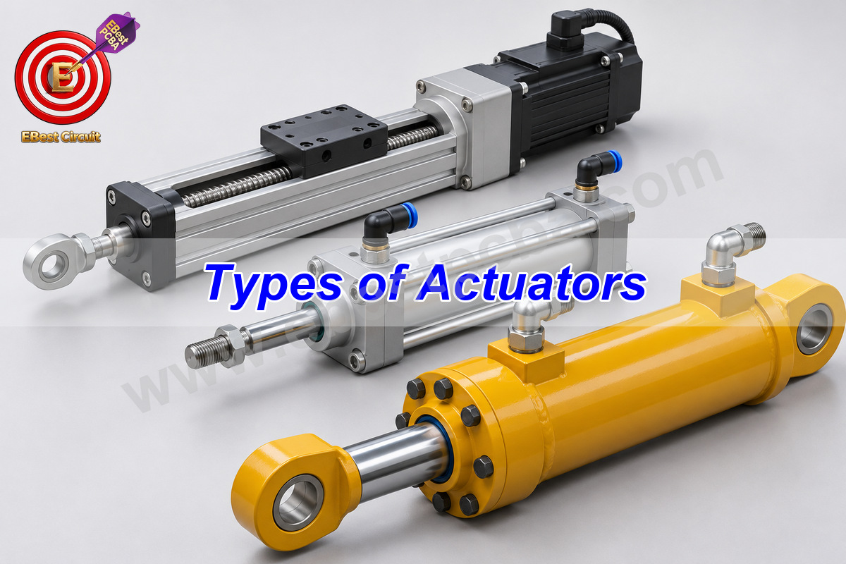
The main types of actuators are electric, pneumatic, hydraulic and mechanical. To choose one, first picture the job. A fixture may need to push a part against a stop, a robot arm may need to turn to a set angle, and a lift may need to hold its load when power drops. Those jobs call for different motion, force and controls.
Key Takeaways
- Decide whether the load needs straight travel or a turn before choosing a power source.
- Size the cylinder for the weaker stroke if it must move the load both ways.
- Check where the load stops and what it does when power or pressure drops.
What Are the Main Types of Actuators and Their Functions?
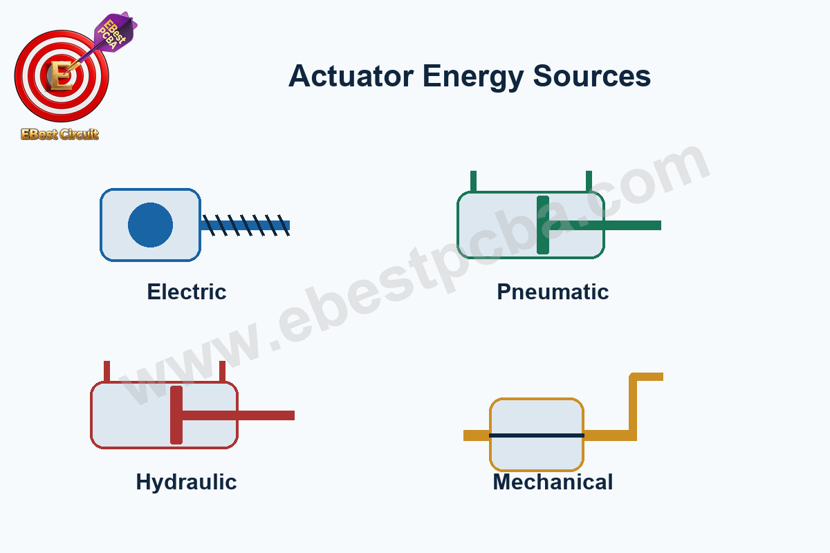
The types of actuators and their functions are easier to see in a machine. An electric screw moves a carriage, compressed air moves a clamp, hydraulic fluid moves a press ram, and a hand crank moves an adjustment screw. The four types differ in what supplies the motion.
| Type | Input | Common jobs | Main constraint |
|---|---|---|---|
| Electric | Electrical supply and driver | Robot joints, positioning slides and valve drives | Motor heating, peak current and transmission life |
| Pneumatic | Compressed air | Fast clamping, ejection and end-to-end movement | Available pressure and flow; compressibility |
| Hydraulic | Pressurized fluid | Heavy lifting, forming and high-load cylinders | Hydraulic power unit, leakage and maintenance |
| Mechanical | Manual or external mechanical input | Adjustment screws, cam mechanisms and latches | Manual effort or a separate source of motion |
How Do Linear and Rotary Actuators Differ?
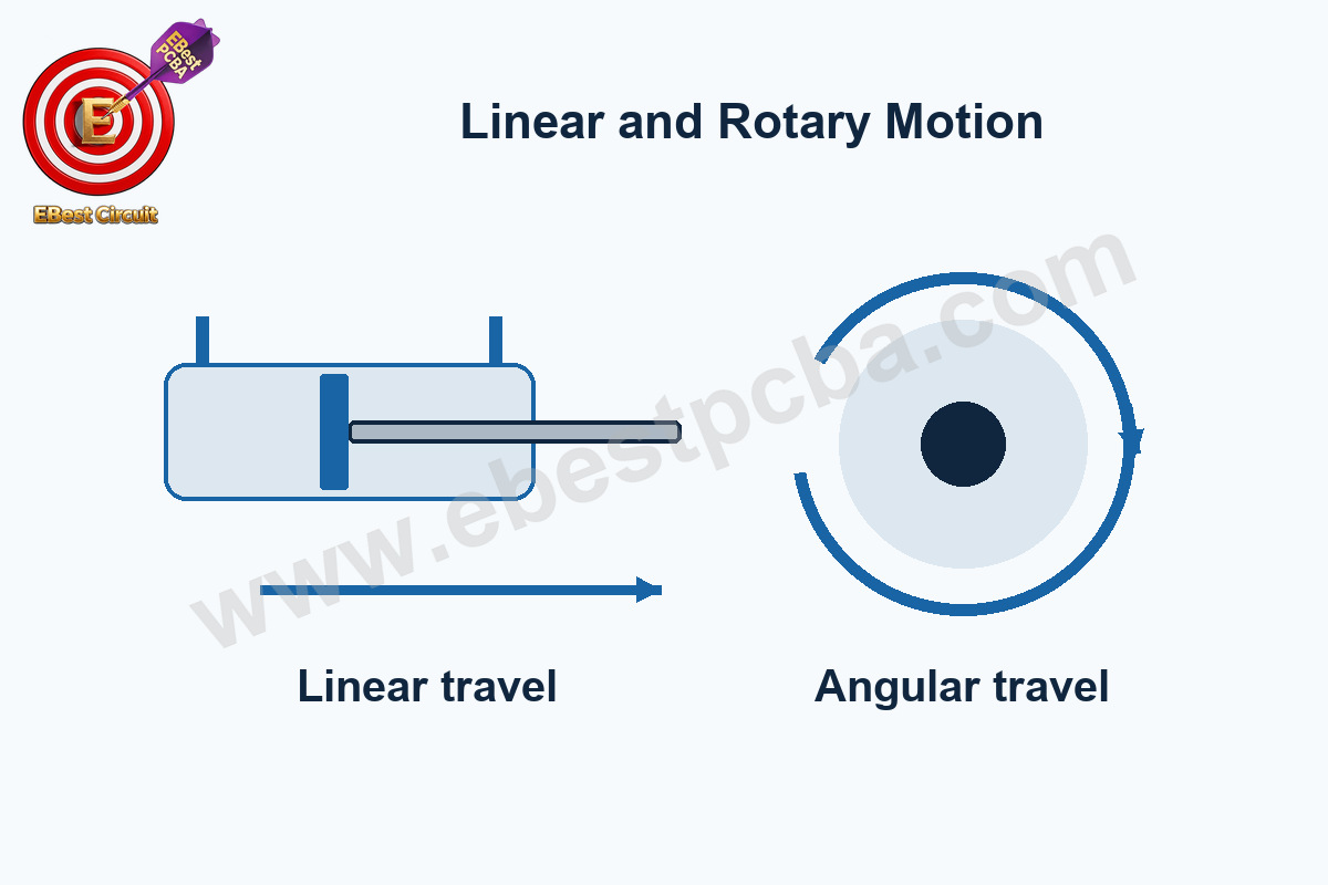
A linear actuator moves in a straight line, like a rod pushing a drawer. A rotary actuator turns a shaft, like a drive opening a valve through 90°. The same motor can drive either motion. Attach it to a shaft and the output turns. Attach it to a screw and a guided nut and the output travels along the screw.
For a straight move, write down force, stroke and speed. For a turn, write down torque, angle and speed. Also note where the load acts. A force that pushes sideways on a cylinder rod can overload the guide even when the cylinder can easily push the same force along its axis.
How Do You Choose Between a Screw, Belt and Fluid Cylinder?
Use the move you need to make to narrow the choice. A screw stage can provide controlled travel under load at relatively low speed. A belt stage may suit a longer or faster move. Check how the belt stretches under the load and whether the carriage can settle within the position tolerance.
A pneumatic cylinder and two end sensors may be enough for a clamp that only opens and closes. If the same axis must stop at several positions, compare a guided electric stage with a controlled pneumatic system. Include the valves or drive, guides and supply in the comparison.
| Motion requirement | Candidate | Verify first |
|---|---|---|
| Move a part between two stops | Pneumatic cylinder | Cycle time at available flow and pressure |
| Position at multiple points | Electric screw or belt axis | Repeatability under load and move profile |
| Apply high force over a stroke | Hydraulic cylinder | Push and pull force, fluid supply and mounting |
| Set position manually | Mechanical screw or cam | Travel, effort and holding behavior |
How Do You Estimate the Force and Speed You Need?
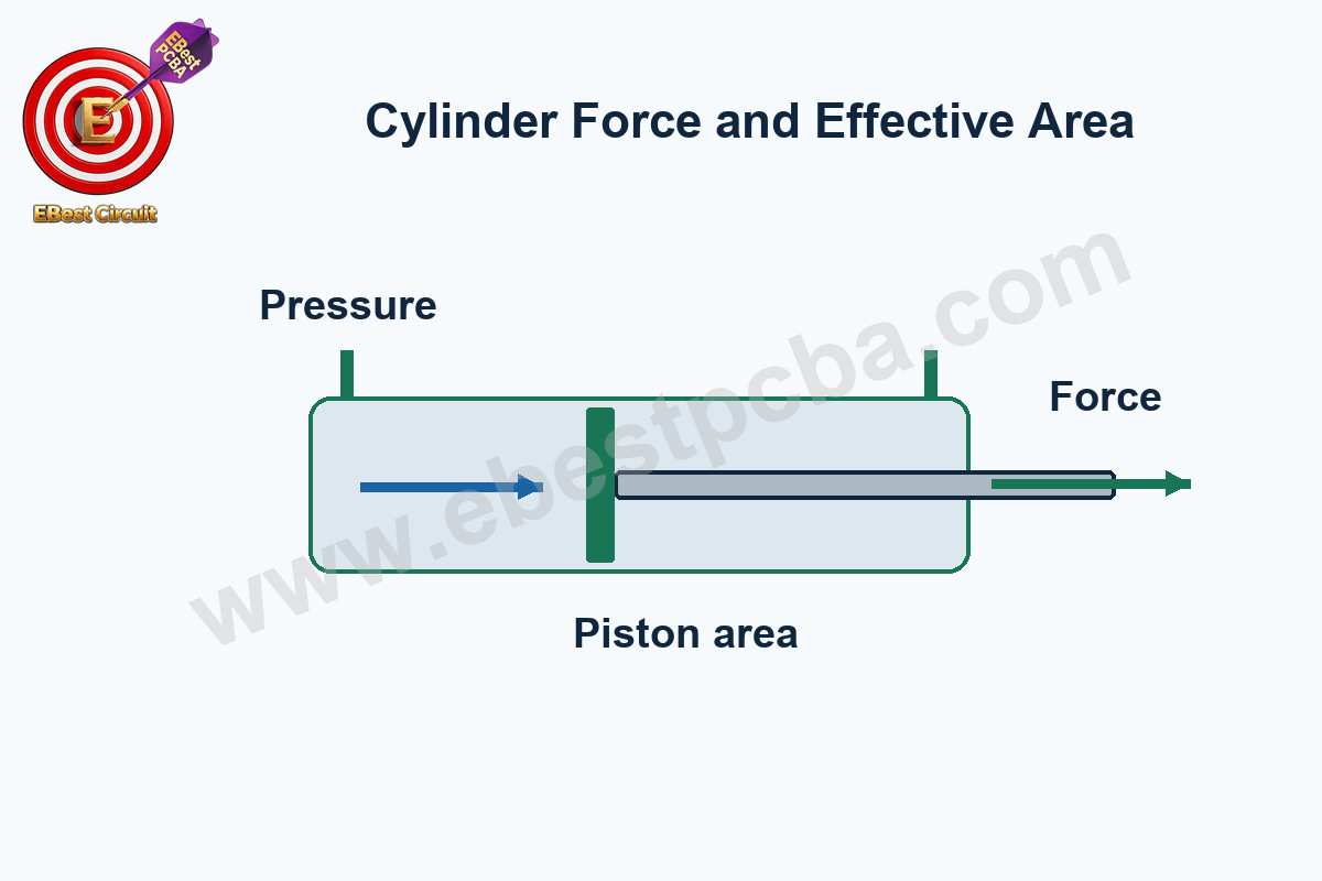
Estimate cylinder force using the pressure difference across the piston and the effective area on each side. The rod occupies part of the retracting side. Subtract its area when you estimate pull force.
» F ≈ Δp × A
A 32 mm bore gives about 804 mm² of full piston area. At a pressure difference of 0.5 MPa, the ideal push force is about 402 N. Compare that with the moving load after allowing for friction, acceleration and pressure loss. Check the actual pressure at the cylinder during travel.
How Do Stroke, Retraction Force and Cycle Time Change the Sizing?
With a 12 mm rod, the same cylinder has about 691 mm² on the retract side. At 0.5 MPa, the ideal pull force is about 346 N. If the return stroke does the work, size against that lower figure.
If the load must move 150 mm in half a second, it averages 300 mm/s. The drive must go faster than that if acceleration and braking are included in the half-second. Check the valve and tube flow for a fluid cylinder, or the force available at peak speed for an electric axis.
For a rotary joint, imagine 40 N pulling at right angles to a 150 mm arm. That load alone needs 6 N·m of holding torque. Check the largest moment over the whole move, then allow for friction and acceleration.
What Are the Main Types of Actuators in Robotics?
The types of actuators in robotics depend on the joint. An electric rotary servo can turn an arm joint to a known angle. A linear stage can move a camera along a rail. A pneumatic gripper can open and close at two stops. Some large machines use hydraulic cylinders where the load calls for more force.
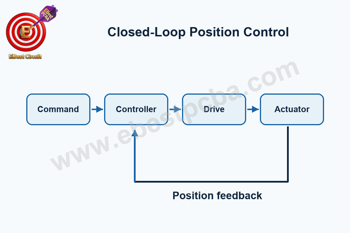
An actuator is the part that moves the load. In a servo system, a sensor reports the position and a controller compares it with the command. When a gripper is rated at the cylinder rod, check the force at the jaws as well. The linkage can change what reaches the part.
How Do You Verify Repeatability and Power-Loss Behavior?
Test the complete mechanism with the load in place. Approach the same position from both directions and measure where the load settles. If it stops consistently at the wrong position, it is repeatable but needs an accuracy correction. If it stops in a different place each time, check backlash, compliance and feedback.
- Run the minimum and maximum expected loads through the intended motion profile. Record position, current or pressure, and cycle time.
- Compare motion from both directions, including reversal and the first move after a cold start.
- Check the end sensors and mechanical travel limits independently; the controller should not rely on a single unverified position reading.
- Verify the specified behavior when supply power, air pressure or command is lost. A vertical axis or stored-energy mechanism needs an engineered holding or release strategy appropriate to the machine.
Write the pass limits beside the measurements. Include the load, supply conditions and allowed error at the end of the cycle. If a fixture only checks that the driver switches, reserve the loaded motion and power-loss checks for the completed machine.
What Must the Controller and Actuator Agree On?
Before wiring the controller, check the actuator’s supply, command and feedback. A reversing DC motor needs a driver that can carry current in either direction. A valve coil may need a clamp across its electrical path, and the clamp can affect how quickly the valve releases. A vertical load also needs a defined way to hold or lower the load if power drops.
For an industrial control PCB assembly, send the actuator and driver part numbers, current profile and command sequence with the DFM review. Use those inputs to specify what assembly inspection and testing should verify.
Frequently Asked Questions
Is an actuator the same as a servo?
The actuator moves the load. A servo uses feedback to adjust that motion. An electric screw actuator with an encoder can be part of a servo axis. A pneumatic cylinder that only travels between stops can move a load without a position servo.
Is a solenoid suitable for precise positioning?
A common on-off solenoid works well for short moves between stops. If a part must stop at several positions under changing load, choose a drive and feedback system specified for that job.
Why does my cylinder meet the force estimate but move too slowly?
A force estimate uses pressure and piston area. Speed also depends on how quickly the chamber fills and exhausts. Check the valve, tube size and pressure at the cylinder while it moves.
Can a lead screw hold a vertical load with power off?
Some screws resist backdriving. Verify it for the exact screw, load and operating conditions. Use the specified brake or retention mechanism when the machine requires a reliable hold.
How should I specify duty cycle for an electric actuator?
Record how long it moves, how long it rests, the load and how often the cycle repeats. Also state whether the motor holds the load during the rest period. That holding current can contribute to heating.
How do I tell a driver fault from a jammed actuator?
Compare the command, drive current and position at the same time. A valid command with no current points toward the electrical path or the driver. Current with no movement calls for a check of the load, mechanism and actuator.