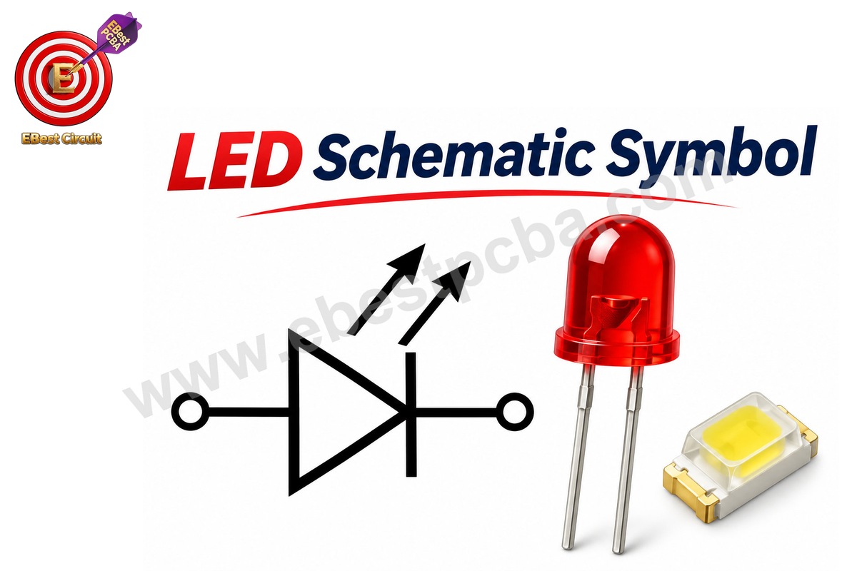
The LED schematic symbol represents a light-emitting diode in an electrical circuit. It combines a diode symbol with 2 outward-pointing arrows to indicate light emission. The symbol also identifies the anode (positive terminal during forward conduction) and cathode (negative terminal during forward conduction), helping engineers connect LEDs correctly in circuit diagrams. Understanding LED schematic symbol meaning starts with the cathode bar and outward arrows. To read LED schematic symbol positive and negative terminals, identify anode and cathode labels. This guide explains LED symbol polarity, arrow direction, IEC standards, resistor circuits, RGB and IR LED symbols, and how schematic connections translate into PCB footprints.
At EBest PCBA, we provide PCB fabrication, LED component sourcing, SMT/DIP assembly, and functional testing for electronic products. Our capabilities include Free DFM, No MOQ, 4 SMT lines, 01005 component assembly, and MES single-board traceability. A dedicated team of 1 sales representative and 3 engineers coordinates design reviews, component requirements, and manufacturing support. For LED PCB assembly projects, send your Gerber files, BOM, quantities, and testing requirements to sales@ebestpcba.com for a project-specific engineering review and quotation.
Key Takeaways
- The LED schematic symbol consists of a diode symbol with 2 arrows pointing outward, representing the emission of light when the LED is forward-biased.
- LED polarity is determined by the anode (A) and cathode (K). The cathode is identified by the vertical bar in the schematic symbol, while conventional forward current flows from anode to cathode.
- The 2 arrows on an LED symbol indicate light emission, rather than electrical current direction. A photodiode uses inward-pointing arrows to indicate light reception.
- IEC 60617 defines the general LED symbol, which is widely recognized in electrical schematics and electronic design software.
- A simple LED circuit uses a current-limiting resistor to control forward current. The resistance can be calculated using the supply voltage, LED forward voltage, and target current.
- RGB LED schematic symbols represent 3 color channels: red, green, and blue. Common-anode and common-cathode RGB LEDs require different driving arrangements.
- Red, green, blue, IR, and UV LEDs use the same basic emission symbol, with device-specific labels or component specifications identifying their optical characteristics.
- LED schematic pins must match the PCB footprint pads and physical component polarity. Correct symbol-to-footprint mapping, BOM verification, and assembly inspection help prevent reversed LED placement and incorrect connections.
What Is the LED Schematic Symbol and What Does It Mean?
The LED schematic symbol is a diode symbol with 2 small arrows pointing away from it, indicating that the electronic component emits light. The diode portion represents its electrical behavior, while the outward arrows distinguish an LED from an ordinary rectifier or signal diode.
LED stands for Light-Emitting Diode, a semiconductor device that converts electrical energy into light when operated under suitable forward-bias conditions.
A standard LED schematic symbol contains 3 essential elements:
- Diode Symbol: Represents the semiconductor junction and its electrical polarity.
- Cathode Bar: Identifies the cathode terminal of the LED.
- Outward Arrows: Indicate light being emitted from the device.
The outward arrows describe optical emission. They are separate from the electrical current path through the diode.
How Does an LED Work in a Circuit?
An LED contains a semiconductor junction that emits photons when electrons and holes recombine under forward-bias conditions.
In a typical indicator circuit, the electrical sequence is:
- The power supply establishes a forward voltage across the LED.
- Current flows from the anode toward the cathode.
- The semiconductor junction produces light.
- A resistor or LED driver regulates the operating current.
LEDs are available in different colors, sizes, optical outputs, and package styles. Their basic schematic representation remains similar even when their physical appearance changes.
What Does D1 or LED1 Mean on a Schematic?
Electrical schematics use reference designators to identify individual components.
For LEDs, common examples include:
| Reference | Meaning |
|---|---|
| D1 | Diode or LED number 1 |
| D2 | Diode or LED number 2 |
| LED1 | LED number 1 |
| LED2 | LED number 2 |
The designator identifies the component’s position in the circuit documentation. Its actual color, electrical rating, package, and manufacturer part number are normally specified through component properties and the bill of materials (BOM).
For example, LED1 could represent a red indicator LED, a white SMD LED, or an infrared emitter. The reference designator alone does not establish the device specifications.
How Do You Identify Positive and Negative on an LED Circuit Symbol?
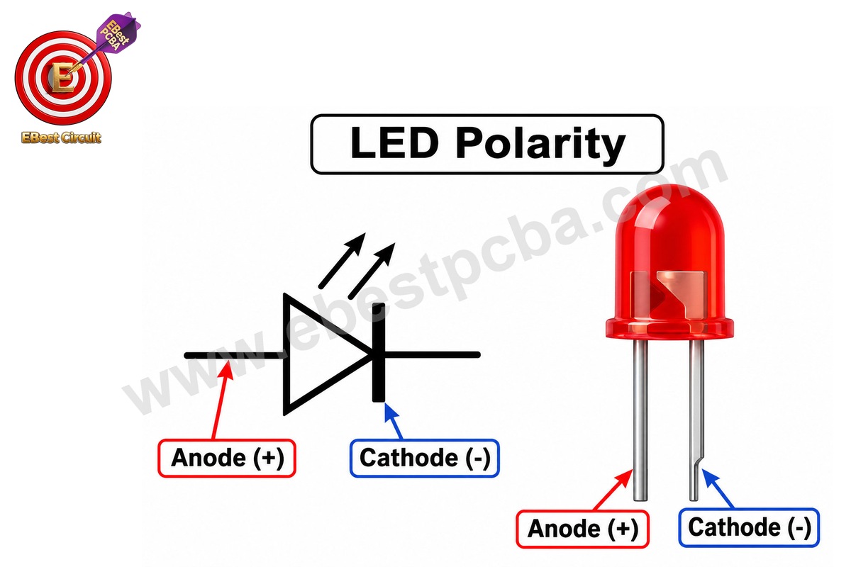
The anode (A) is the positive terminal and the cathode (K) is the negative terminal during normal forward operation. In an LED schematic symbol, the vertical bar represents the cathode. Conventional forward current enters through the anode and exits through the cathode.
An LED is a polarized component, so its electrical orientation matters when connecting the circuit.
| LED Terminal | Symbol Identification | Forward Current |
|---|---|---|
| Anode (A) | Side opposite cathode bar | Enters LED |
| Cathode (K) | Side with vertical bar | Leaves LED |
1. Identify the Anode
The anode is the terminal where conventional current enters the LED during forward conduction. In a simple DC indicator circuit, the anode is commonly connected toward the positive supply through a current-limiting resistor.
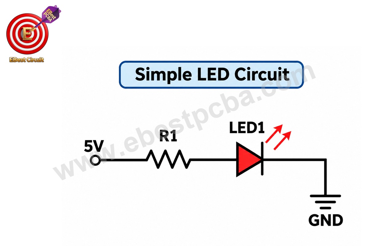
For example: +5 V → Resistor → LED Anode → LED Cathode → GND
This arrangement allows the LED to conduct when the supply voltage and series resistance establish a suitable forward current.
2. Identify the Cathode
The cathode is represented by the bar side of the diode symbol. In many simple circuits, it connects toward the negative supply or ground. However, a cathode can also connect to a transistor, MOSFET, microcontroller output, or constant-current driver.
For example, in a low-side switching circuit, the LED cathode may connect to the drain or collector of a switching device rather than directly to GND. The schematic symbol remains unchanged because anode and cathode refer to component terminals, not fixed power-supply connections.
3. Identify Polarity on a Physical LED
The physical markings depend on the LED package. Common through-hole LEDs may use:
- Longer lead: Often indicates the anode.
- Shorter lead: Often indicates the cathode.
- Flat package edge: Commonly indicates the cathode side.
For SMD LEDs, polarity indicators can include a printed line, dot, chamfer, corner marking, or package-specific shape. These conventions vary, so the manufacturer’s datasheet should take priority over appearance alone.
4. Confirm Polarity Before Assembly
A practical verification process includes:
- Locate the anode and cathode in the schematic.
- Check the symbol pin numbers.
- Compare the footprint pad numbers.
- Review the LED package orientation drawing.
- Verify the placement data and assembly drawing.
A multimeter diode-test function can also help identify polarity for many LEDs, although its available test voltage may be insufficient to illuminate certain devices or multiple LEDs connected in series.
What Do the Arrows and Direction of an LED Schematic Symbol Mean?
The 2 arrows pointing outward from an LED schematic symbol indicate light emission. They show that the component produces optical radiation during operation. These arrows do not identify the electrical current direction or the positive and negative terminals.
The LED’s anode and cathode determine its electrical polarity, while the arrows describe the optical function.
1. LED vs Diode vs Photodiode
These components share related semiconductor symbols, but their arrow markings differ.
| Component | Symbol Feature | Main Function |
|---|---|---|
| Standard Diode | Diode symbol | Directional conduction |
| LED | 2 outward arrows | Emits light |
| Photodiode | 2 inward arrows | Detects light |
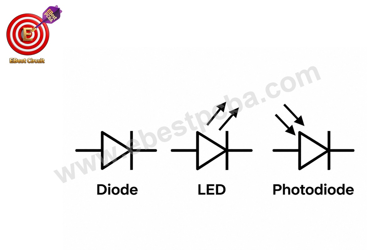
A standard diode symbol has no optical emission arrows. An LED adds outward arrows to indicate light generation. A photodiode uses inward arrows to represent incoming light reaching the semiconductor junction.
This distinction is especially useful in circuits containing optical transmitters and receivers. For example, an infrared communication circuit may contain an IR LED for transmission and a photodiode or phototransistor for reception.
2. Does LED Symbol Orientation Change Its Polarity?
The LED symbol can be rotated or mirrored when drawing a schematic. Its cathode does not always appear on the right, and its anode does not always appear on the left.
When checking polarity, look for the cathode bar and the component’s pin designation rather than assuming a fixed drawing direction. This is particularly important in CAD schematics with vertically oriented LED symbols or multiple LED branches.
3. Do Outward Arrows Represent Brightness?
No. The arrows indicate light emission, but their length, size, or drawing angle does not normally represent brightness.
LED brightness and optical output are specified using datasheet parameters such as:
- Luminous intensity
- Luminous flux
- Radiant intensity for relevant devices
- Forward current
- Viewing angle
- Dominant wavelength or chromaticity
A high-power white LED and a low-current indicator LED may use the same basic symbol despite having very different electrical and optical specifications.
What Is the Standard LED Symbol Under IEC 60617?
IEC 60617 identifies the general light-emitting diode symbol as a diode symbol with 2 outward-pointing arrows. This standardized representation helps engineers recognize LED components consistently across electrical diagrams, technical documentation, and electronic design tools.
The IEC 60617 symbol database includes the general LED symbol under reference S01919, covering the representation of light-emitting semiconductor devices.
1. What Does the IEC LED Symbol Include?
The symbol communicates 2 functions:
- Electrical function: A diode with anode and cathode terminals.
- Optical function: Light emission represented by outward arrows.
The symbol establishes the component category. It does not specify LED color, package dimensions, rated current, or forward voltage. Those characteristics are documented separately.
2. How Is the LED Symbol Used in CAD Software?
Electronic design software such as KiCad and Altium Designer provides schematic symbols for LEDs. When placing an LED symbol in a circuit, engineers generally assign:
- Component reference designator.
- Manufacturer part number or component value.
- Electrical pin numbers.
- PCB footprint.
- Additional BOM information.
The visible drawing can be rotated to suit the schematic layout while preserving the component’s electrical connectivity. For example, an LED may appear vertically between a resistor and ground or horizontally between a driver output and supply rail. Both arrangements are valid when the pin connections are correct.
3. Why Do Symbol Standards Matter in PCB Design?
Consistent symbols improve communication between schematic design, PCB layout, component sourcing, and assembly teams. The important checks include:
- Standardized component identification.
- Consistent anode and cathode definitions.
- Matching schematic pin numbers and PCB pad numbers.
- Correct footprint assignment.
- Accurate assembly documentation.
These checks are particularly valuable when transferring designs between CAD libraries, engineering teams, or contract manufacturers. The symbol is only the starting point. Correct electrical pin mapping determines whether the manufactured board follows the intended circuit.
How to Draw a Simple LED Circuit Diagram with a Resistor?
A simple LED circuit diagram uses an LED and a current-limiting resistor connected in series with a power supply. The resistor controls forward current, helping the LED operate within its electrical ratings.
The basic connection is: +5 V → R1 → LED1 (Anode → Cathode) → GND.
The resistor may be installed on either side of the LED within the same series current path.
1. Calculate the LED Resistor Value
The resistor can be calculated using:
» R = (VS − VF) / IF
Where:
- R = Series resistance in ohms.
- Vₛ = Supply voltage.
- Vꜰ = LED forward voltage.
- Iꜰ = Target LED forward current.
For a simple red LED indicator circuit, assume:
| Parameter | Example Value |
|---|---|
| Supply Voltage | 5 V |
| LED Forward Voltage | 2 V |
| Target Forward Current | 10 mA |
| Calculated Resistance | 300 Ω |
The calculation is:
» R = (5 − 2) / 0.01 = 300 Ω
Therefore, the calculated current-limiting resistance is 300 Ω. A common standard resistor value of 330 Ω provides a slightly lower nominal current:
» IF = (5 − 2) / 330 = 0.00909 A
» IF ≈ 9.1 mA
This is an illustrative design calculation. The actual LED forward voltage changes with current, temperature, and component variation.
2. Check the Resistor Power Rating
Resistor power dissipation can be estimated using:
» PR = IF2 × R
For a 330 Ω resistor carrying approximately 9.1 mA:
» PR = (0.00909)2 × 330
» PR ≈ 0.027 W = 27 mW
This nominal dissipation is approximately 27 mW. A properly selected resistor should provide suitable power margin under the expected operating and environmental conditions.
3. Why Does an LED Need a Current-Limiting Resistor?
An LED’s forward current increases rapidly as applied forward voltage rises. Connecting an ordinary LED directly across a voltage source can allow excessive current to flow.
A series resistor helps establish a more predictable operating current when the supply voltage is sufficiently higher than the LED forward voltage. For higher-power lighting circuits, constant-current LED drivers are often preferred because they regulate current despite changes in LED characteristics and operating conditions.
Some LED modules already contain internal current-limiting circuitry. Their datasheets define required external connections.
4. Can Multiple LEDs Share 1 Resistor?
Multiple LEDs connected in series can share 1 current-limiting resistor when the supply provides sufficient voltage. The approximate resistance becomes:
» R = [VS − (VF1 + VF2 + … + VFn)] / IF
For parallel LED branches, separate current-limiting elements are generally preferable because differences in forward voltage can cause uneven current sharing. The circuit should also account for supply tolerance, LED voltage variation, and the desired brightness range.
How Do You Read an RGB LED Schematic Symbol?
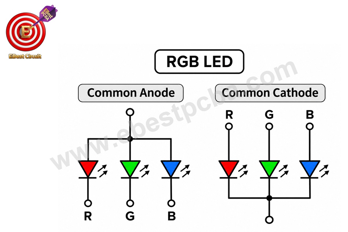
An RGB LED schematic symbol represents 3 LED channels—red, green, and blue—within 1 component or module. Each channel emits a different color, and the combined optical output produces a range of colors.
RGB LEDs are commonly represented using 3 diode symbols with outward arrows. Their electrical arrangement depends on whether the package uses a common anode, common cathode, or independent terminals.
1. Common Anode RGB LED
An RGB LED symbol can show a shared anode or cathode. A common-anode RGB LED connects the anodes of the 3 color channels to a shared terminal. The common terminal connects toward the positive supply, while the individual cathodes are driven separately.
Typical connections include:
- Common Anode: Shared positive supply.
- Red Cathode: Red-channel current control.
- Green Cathode: Green-channel current control.
- Blue Cathode: Blue-channel current control.
A microcontroller or LED driver can control the individual channels through suitable current-sinking circuitry.
2. Common Cathode RGB LED
A common-cathode RGB LED connects the cathodes of the 3 channels to a shared terminal. The shared cathode usually connects toward the negative supply or ground, while each anode is driven separately.
The driver sources current into the selected color channels. The main differences are:
| Feature | Common Anode | Common Cathode |
|---|---|---|
| Shared Terminal | Anode | Cathode |
| Common Connection | Positive supply | Negative supply |
| Channel Driver | Current sinking | Current sourcing |
| Color Control | Individual cathodes | Individual anodes |
3. Does Each RGB LED Channel Need a Resistor?
For a basic RGB LED without internal current regulation, each color channel should have suitable individual current limiting. Red, green, and blue LED junctions often have different forward voltages.
For example, illustrative values might be:
| Channel | Example Forward Voltage |
|---|---|
| Red | 2.0 V |
| Green | 3.0 V |
| Blue | 3.0 V |
These values are examples rather than universal specifications. Using the same resistor value for all channels may produce different currents, depending on forward-voltage characteristics. Independent resistors or properly configured constant-current drivers help achieve controlled operation.
4. How Are RGB LEDs Controlled?
RGB brightness is commonly adjusted using pulse-width modulation (PWM) or dedicated current-control drivers. By varying relative intensity of red, green, and blue channels, a system can produce different colors.
For example:
- Red only: Red channel active.
- Red + Green: Yellow-like output.
- Green + Blue: Cyan-like output.
- Red + Blue: Magenta-like output.
- Red + Green + Blue: White or near-white output, depending on the LEDs.
Color accuracy depends on actual LED wavelengths, intensity ratios, temperature, and optical design.
5. Does Every RGB LED Have 4 Pins?
No. Common-anode and common-cathode RGB LEDs frequently use 4 terminals, but other designs may use 6 independent terminals.
Addressable RGB LEDs can include an integrated driver and use power, ground, data input, and sometimes data output connections. Their schematic symbols must follow the specific component datasheet rather than a generic 4-pin RGB LED arrangement.
How Are IR LED, Red LED, and LED Strip Schematic Symbols Different?
Red LEDs, IR LEDs, UV LEDs, and many other single-junction LEDs use the same basic schematic symbol. The electrical symbol indicates light emission, while the part number, label, and datasheet identify the optical characteristics and application.
LED strips and addressable LED modules may require more complex schematic representations because they contain multiple LEDs or integrated electronics.
| LED Type | Schematic Representation | Key Difference |
|---|---|---|
| Red LED | Standard LED symbol | Visible red output |
| Green LED | Standard LED symbol | Visible green output |
| Blue LED | Standard LED symbol | Visible blue output |
| IR LED | LED symbol with IR identification | Infrared emission |
| UV LED | LED symbol with UV identification | Ultraviolet emission |
| LED Strip | Multiple LEDs or module | Multi-LED arrangement |
| Addressable LED | Device-specific symbol | Integrated control |
1. Red LED Schematic Symbol
A red LED uses the standard light-emitting diode schematic symbol. Its red color is typically identified through a component property, label, description, or part number rather than through a different electrical graphic.
Red LEDs are commonly used in status indicators, warning signals, control panels, and equipment displays. Their operating voltage and current depend on the exact device.
2. IR LED Schematic Symbol
An infrared LED also uses the standard LED emission symbol. The main difference is the optical wavelength, which lies outside the visible spectrum.
Common applications include:
- Remote-control transmitters.
- Infrared communication.
- Optical sensing.
- Position detection.
- Optical encoders.
An IR LED may look similar to an ordinary LED in a schematic, but its forward voltage, wavelength, radiant intensity, switching characteristics, and current ratings depend on the selected component. For pulse-driven IR circuits, peak-current and duty-cycle limits must also be checked.
3. UV LED Schematic Symbol
A UV LED uses the same basic diode-with-emission-arrows representation. Its optical characteristics are identified using wavelength and component specifications.
UV LEDs may be used in sensing, fluorescence, specialized curing, or other industrial applications. The PCB design should account for applicable electrical, thermal, and optical safety requirements.
4. LED Strip Schematic Symbol
An LED strip contains multiple LED packages mounted on a flexible or rigid circuit substrate. Its schematic may show:
- Multiple LEDs connected in series.
- Multiple LED branches connected in parallel.
- Individual current-limiting resistors.
- A constant-current driver.
- A module connector.
For a basic constant-voltage LED strip, a section may contain a group of series-connected LEDs and a resistor. A higher-power strip may use a dedicated LED driver circuit. The schematic representation depends on the actual internal wiring of the strip.
5. Addressable LED Symbol
Addressable LEDs combine light-emitting elements with an electronic driver or controller. A typical addressable RGB device may provide terminals such as VDD, GND, DIN, and DOUT.
However, exact terminal names, pin numbers, and internal structures vary. The correct CAD symbol should be created or selected from the manufacturer’s package and electrical documentation.
How Do You Match an LED Schematic Symbol to Its PCB Footprint?
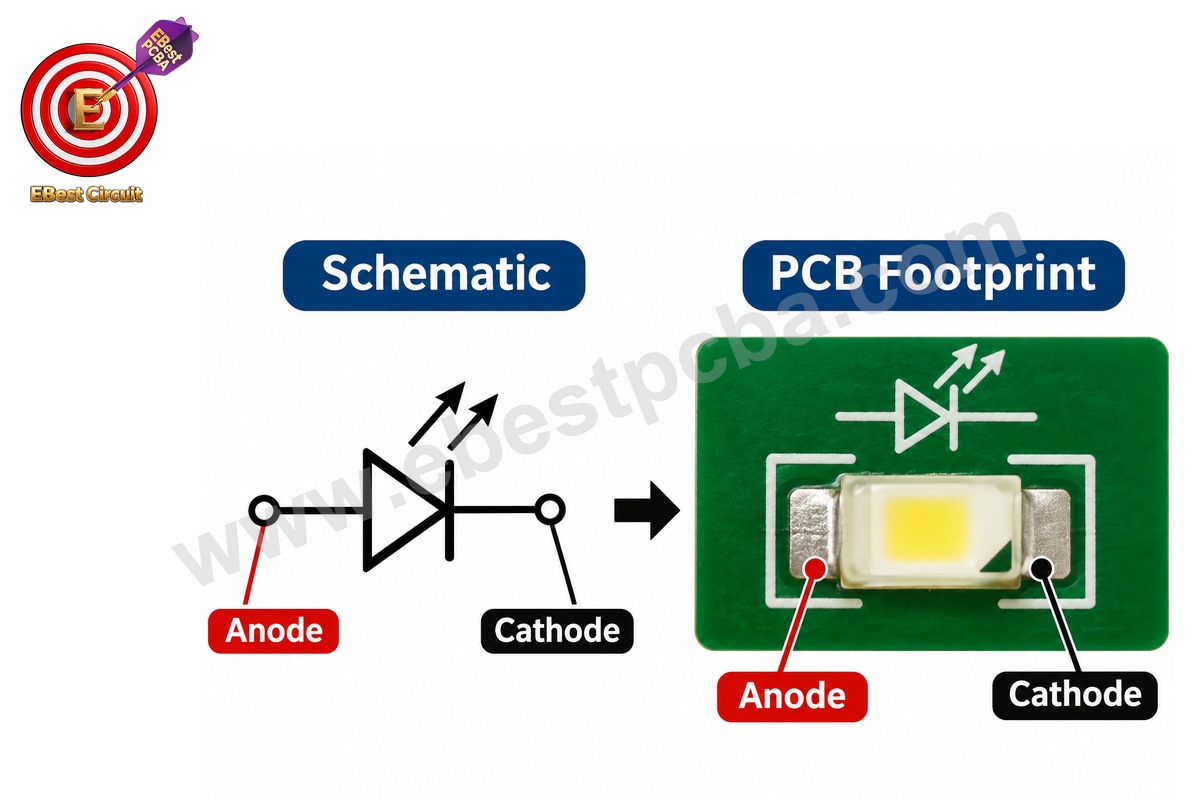
To match an LED schematic symbol to its PCB footprint, the anode and cathode pin numbers in the schematic must correspond to the correct physical pads in the PCB layout. The footprint must also match the selected LED package, dimensions, and mounting requirements.
This mapping connects circuit design to physical PCB assembly: an LED symbol on PCB silkscreen helps communicate orientation, but the approved pin-to-pad mapping remains essential.
1. Verify the Symbol Pin Numbers
In electronic CAD software, a symbol represents the electrical connections of a component. For a simple 2-terminal LED, the symbol contains anode (A) and cathode (K).
The corresponding pin numbers depend on the component library and manufacturer specification. For example, a particular LED may define:
| Schematic Pin | Function | PCB Pad |
|---|---|---|
| 1 | Cathode | Pad 1 |
| 2 | Anode | Pad 2 |
This is only an example. Other LED packages may assign functions differently. The approved datasheet and footprint library determine actual mapping.
2. Select the Correct LED PCB Footprint
LEDs are available in many package sizes and construction types. Common SMD package designations include:
- 0603
- 0805
- 1206
- 2835
- 3528
- 5050
These package designations help identify general dimensions or product families, but the recommended solder pad geometry should come from the selected manufacturer’s datasheet. Two LEDs with similar nominal package dimensions may have different electrical pads, thermal pads, or polarity markings.
3. Match the LED Polarity Markings
Physical LED polarity markings vary among manufacturers and packages. The PCB design should clearly communicate orientation using appropriate silkscreen, assembly documentation, and CAD data.
Important checks include:
- Identify the anode and cathode from the datasheet.
- Confirm schematic pin-to-footprint pad mapping.
- Check physical package markings.
- Verify footprint orientation on the PCB.
- Confirm placement rotation and assembly-view conventions.
A polarity indicator should remain unambiguous after the component is installed.
4. Check the BOM Before Assembly
The BOM should identify the approved LED part number and key electrical characteristics.
| BOM Item | Required Information |
|---|---|
| Reference | D1 / LED1 |
| Manufacturer Part Number | Exact approved MPN |
| LED Color | Red / Green / Blue / White |
| Forward Voltage | Datasheet value |
| Forward Current | Rated operating requirement |
| Package | Exact SMD or THT type |
| Quantity | Required pieces |
For RGB LEDs, the BOM should also identify the common-terminal configuration and package pinout. Incorrect part selection can cause polarity errors, unexpected brightness, color differences, or mechanical assembly issues.
5. Verify Pick-and-Place Orientation
During SMT assembly, the pick-and-place machine uses placement coordinates and rotation information to position the LED on the PCB. However, CAD orientation and component tape orientation may use different reference conventions.
The assembly team should confirm correct physical orientation through approved placement data, component drawings, and first-article verification.
6. Inspect the Assembled LED PCB
Different inspection methods provide different types of quality information.
- SPI: Checks solder paste deposits before component placement.
- AOI: Helps detect missing LEDs, placement errors, visible polarity issues, and selected solder defects.
- Electrical Testing: Measures appropriate electrical conditions where test access permits.
- Functional Testing: Confirms LED operation, color, brightness-related requirements, and control behavior under defined test conditions.
AOI alone cannot prove that every LED meets its optical specifications. Where necessary, functional testing should include suitable current measurements or optical verification.
At EBest PCBA, our engineering team can review LED symbol mapping, footprint compatibility, BOM data, component orientation, and assembly requirements before manufacturing. Our SMT production and inspection processes support the transition from approved schematic documentation to assembled LED PCBs.
Why Choose EBest PCBA for LED PCB Assembly?
EBest PCBA provides coordinated LED PCB fabrication, component sourcing, SMT/DIP assembly, and testing services, helping customers move from circuit design to completed electronic assemblies. Our engineering team supports component verification, footprint review, and manufacturing planning to reduce avoidable design-to-production issues.
Whether you need a compact LED indicator PCB, an RGB lighting controller, or a larger LED circuit assembly, our services can be matched to your project requirements.
- Free DFM Review: Our engineers check LED footprint selection, polarity mapping, pad design, component clearances, and other manufacturing-related details before production.
- No MOQ Support: We support engineering prototypes, small-batch validation, and subsequent production orders without a fixed minimum order quantity.
- 4 SMT Production Lines: Our 2 JUKI and 2 YAMAHA SMT lines provide automated placement capabilities for different PCB assembly requirements.
- 01005 Component Assembly: Our fine-pitch and miniature-component capabilities support compact LED control and driver circuits where appropriate.
- LED Component Sourcing: We coordinate sourcing for approved LEDs, resistors, connectors, driver ICs, and supporting electronic components according to the project BOM.
- SMT and Through-Hole Assembly: We support SMD LED packages, through-hole indicators, and mixed-technology boards using suitable manufacturing processes.
- Inspection and Functional Testing: Available capabilities include SPI, AOI, X-Ray inspection where appropriate, ICT, and FCT based on project-specific requirements.
- MES Single-Board Traceability: Our production tracking system supports board-level manufacturing information retrieval and quality investigation.
- 1 Sales Representative + 3 Engineers: A dedicated project communication structure helps coordinate drawing revisions, component questions, manufacturing requirements, and production updates.
Our operations are supported by quality management certifications, including ISO 9001, ISO 13485, IATF 16949, and AS9100D, with applicable scope available for customer supplier qualification.
If your project involves an LED PCB, RGB LED assembly, LED driver circuit, SMD LED board, or complete electronic assembly, send your Gerber files, BOM, pick-and-place data, quantities, and test requirements to sales@ebestpcba.com. EBest PCBA can review your design and provide a project-specific manufacturing quotation and delivery plan.
Frequently Asked Questions About LED Schematic Symbols
1. What does the LED symbol look like in a circuit diagram?
The LED symbol looks like a standard diode symbol with 2 arrows pointing outward. The diode graphic identifies the semiconductor device and its electrical polarity, while the arrows indicate light emission. An LED is commonly labeled D1 or LED1 in a schematic, with its exact electrical specifications provided in the BOM or datasheet.
2. Is the cathode always on the right side of an LED symbol?
No. The cathode can appear on the left, right, top, or bottom depending on how the schematic symbol is rotated or mirrored. The cathode is identified by the bar in the diode symbol. Engineers should verify anode and cathode labels rather than relying on the symbol’s position.
3. What is the difference between an LED and a photodiode symbol?
An LED symbol uses outward-pointing arrows to represent light emission, while a photodiode symbol uses inward-pointing arrows to represent incoming light. Both use a diode-based graphic, but their primary functions differ. An LED converts electrical energy into light, while a photodiode converts incident light into an electrical response.
4. Is the LED schematic symbol different for SMD and through-hole LEDs?
No. Standard 2-terminal SMD and through-hole LEDs generally use the same basic electrical schematic symbol. Their physical differences are represented through the assigned PCB footprint and component specifications. Engineers must verify package dimensions, pad numbers, polarity markings, and assembly requirements for the selected device.
5. How do you identify the cathode of an SMD LED?
Check the manufacturer’s datasheet and package orientation drawing. SMD LEDs may use a printed line, dot, chamfer, corner marking, or other polarity indicator. These markings are not universal across all LED packages. Compare physical markings with the PCB footprint and approved assembly drawing before installation.
6. Can you connect an LED directly to a battery without a resistor?
A conventional LED generally needs a suitable current-limiting method, such as a series resistor or regulated current driver. Directly connecting it to a battery can produce excessive current, depending on battery voltage, internal resistance, and LED characteristics. LED modules with built-in current regulation may have different requirements specified by their manufacturer.
7. Is an LED bulb symbol the same as a single LED schematic symbol?
Not necessarily. A single LED schematic symbol represents an individual light-emitting diode, while an LED bulb or lighting fixture may contain multiple LEDs, a driver, and other circuitry. Lighting plans may use a lamp or fixture symbol rather than a semiconductor diode symbol. The appropriate representation depends on whether the drawing describes an electronic circuit or a lighting installation.
Conclusion
The LED schematic symbol provides a standardized way to identify light-emitting diodes, determine anode and cathode polarity, and understand the role of LEDs in electrical circuits. Correct interpretation of the outward arrows, IEC symbols, RGB arrangements, current-limiting requirements, and PCB footprint mapping helps engineers produce accurate designs and assembly documentation. At EBest PCBA, our Free DFM, No MOQ support, 4 SMT lines, component sourcing, inspection, and functional testing services help customers bring LED circuit designs into production. Send your project files and requirements to sales@ebestpcba.com for engineering support and a tailored PCB assembly quotation.